Chapter 1: System Components
1.1 System Architecture
The lightning protection and earthing system for network and data facilities is organized as a four-layer architecture. Each layer addresses a distinct physical or operational concern, and all layers must be designed and implemented together to achieve coordinated protection. The architecture is anchored at the bottom by the earth electrode system and progresses upward through surge protection, EMC routing, and monitoring layers.
The architecture follows the principle that surge energy must be given a controlled, low-impedance path to earth — away from sensitive equipment. This is achieved by placing the Main Equipotential Bonding Bar (MEB) at the center of the design, connecting all metallic structures, SPD earth leads, and shield terminations to a single common reference. The three-zone building layout (Entrance/External, DMZ/Aggregation, Core/Equipment) provides both electrical and logical segmentation, with fiber boundaries preferred at zone transitions to break the conductive surge path.
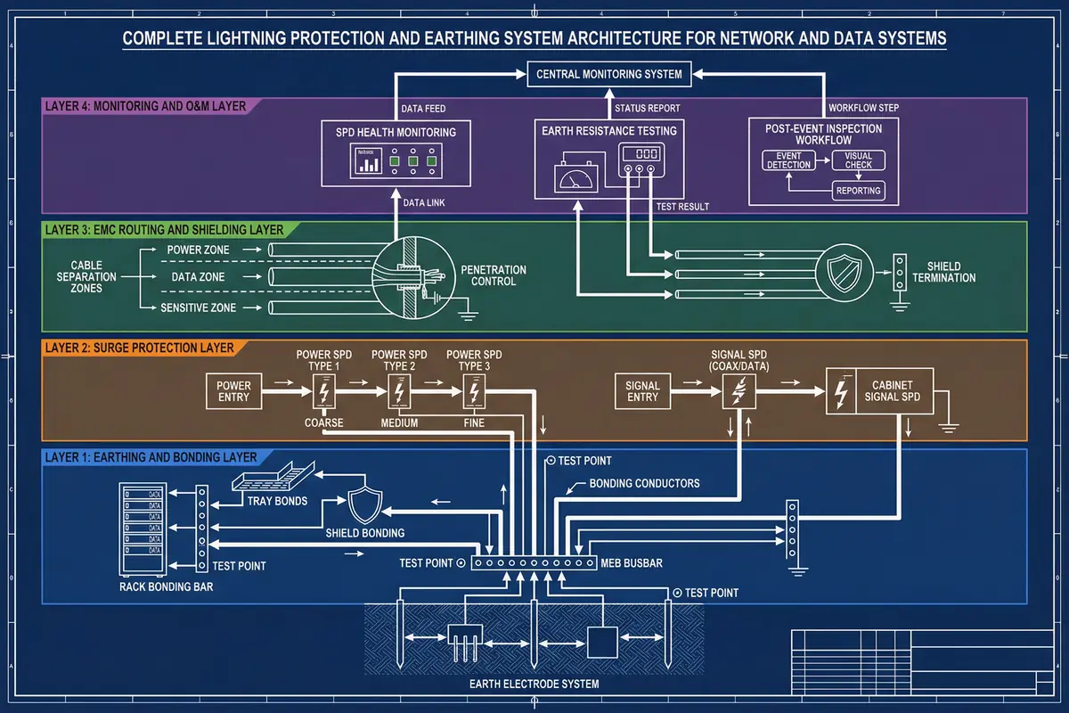
Layered Responsibilities
The four layers each carry distinct responsibilities that together form a complete protection system. The earthing and bonding layer provides the physical foundation, while the surge protection layer intercepts and diverts transient energy. The EMC routing and shielding layer minimizes inductive coupling, and the monitoring and O&M layer ensures the system remains effective throughout its operational life.
| Layer | Primary Responsibility | Key Components | Acceptance Focus |
|---|---|---|---|
| Layer 1: Earthing & Bonding | Provide common equipotential reference; dissipate surge energy to earth | Earth electrode system, MEB, bonding conductors, rack bonding bars, tray bonds, test points | Continuity measurements; visual verification; test point accessibility |
| Layer 2: Surge Protection | Intercept and clamp overvoltages on power and signal lines | Type 1/2/3 power SPDs, signal SPDs (Ethernet, RS-485, coax), backup protection devices | SPD class/ratings; lead length; backup device ratings; remote alarm wiring |
| Layer 3: EMC Routing & Shielding | Minimize inductive coupling; control penetrations; terminate shields correctly | Cable separation zones, crossing rules, penetration register, shield bonding clamps | Separation distances; penetration register audit; shield termination method |
| Layer 4: Monitoring & O&M | Detect degradation; maintain protection integrity over time | SPD health contacts, earth resistance test links, post-event inspection SOPs | Alarm simulation test; inspection records; post-event SLA compliance |
Key Data and Control Flows
Network traffic flows from the Entrance Facility through the DMZ to the Core zone. Control and management traffic flows to monitoring systems. Lightning surge energy, by contrast, must flow from external lines to SPDs, then via short leads to the MEB, and then to the earth electrode system — never through equipment chassis or signal cables. This separation of surge current path from data path is the fundamental design principle that all routing and bonding decisions must support.
1.2 Components and Functions
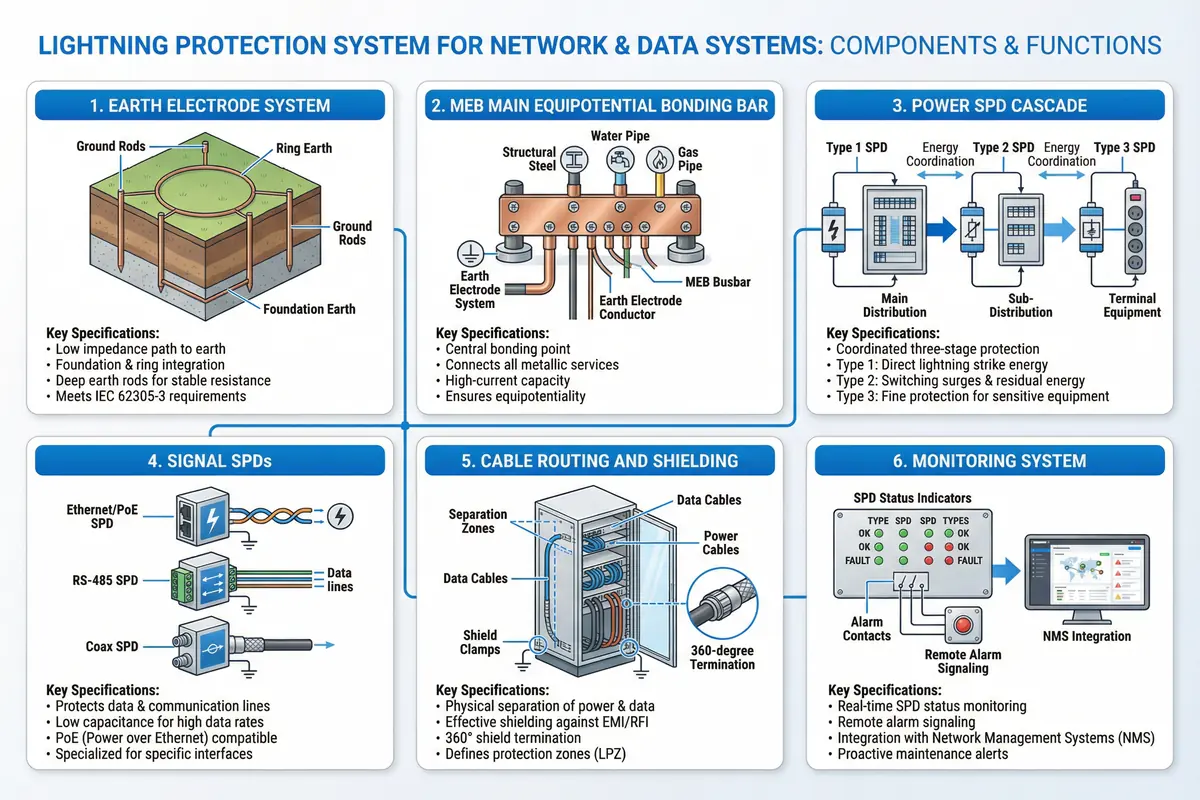
The system comprises six major component groups, each with a specific role in the overall protection scheme. Understanding the function and interdependencies of each component group is essential for correct design, installation, and maintenance. The diagram below provides an overview of all six groups with their key specifications.
A. Earth Electrode System
The earth electrode system provides the ultimate reference potential for the entire protection scheme. It consists of foundation earth electrodes embedded in the building structure, ring earth conductors around the perimeter, and supplementary driven rods where soil conditions require. The critical design parameter is not a single resistance value but rather a low-impedance path that remains stable under impulse conditions. The electrode system must be accessible via a test link for periodic measurement and must be documented with as-built drawings showing electrode locations, depths, and interconnections.
B. Main Equipotential Bonding Bar (MEB)
The MEB is the central hub of the bonding network. It must be located physically close to the service entry and main distribution equipment to minimize SPD lead lengths. All metallic services entering the building — power PE conductors, water pipes, gas pipes, structural steel, HVAC ducts — must be bonded to the MEB. Rack bonding bars connect each equipment rack to the MEB via short, wide bonding conductors. The MEB must have sufficient terminals for all current and future connections, with spare capacity for expansion. Each terminal must be labeled with a unique identifier matching the as-built drawings.
C. Power SPD Cascade (Type 1 / Type 2 / Type 3)
Power surge protection is implemented as a coordinated three-stage cascade. Type 1 SPDs at the service entry handle the highest energy impulse currents from direct strikes or nearby strikes to the building. Type 2 SPDs at room distribution panels reduce the residual voltage after the Type 1 stage and protect downstream distribution and UPS equipment. Type 3 SPDs at rack PDUs or equipment inputs provide fine protection for sensitive electronics. Each stage must be coordinated with the next so that the upstream stage handles the bulk of the energy and the downstream stage sees only the residual. Backup protective devices (fuses or MCBs) must be installed as specified by the SPD manufacturer to prevent overheating in fault conditions.
D. Signal SPDs
Signal line surge protection addresses the three main categories of signal interfaces found in network and data facilities. Ethernet and PoE SPDs protect RJ45 ports from differential and common-mode surges while maintaining the required data bandwidth and PoE power delivery. RS-485 and serial control SPDs protect field device interfaces from long-run induced surges, with compatibility requirements for baud rate and biasing. Coaxial SPDs protect RF equipment and antenna feeders, with insertion loss and frequency range as critical selection parameters. All signal SPDs must be installed at the entry point of the protected zone, with short bonding leads to the nearest bonding bar connected to the MEB.
E. Cable Routing and Shielding
Physical separation between power and data cables reduces inductive coupling and limits the surge energy that can be induced into signal cables. The required separation distance depends on the power level, cable length, and the presence of shielding. Cables must cross at right angles where separation cannot be maintained. Penetrations through walls and floors must be registered, sealed, and routed through the entrance facility to maintain zone integrity. Shield termination method must be defined for each cable type — single-end bonding for low-frequency applications to avoid ground loops, and 360° clamp terminations for high-frequency applications where shield effectiveness is critical.
F. Monitoring System
The monitoring system provides visibility into the health of the protection infrastructure. SPD remote alarm contacts signal when a protection module has operated or degraded, enabling proactive replacement before the next lightning event. Earth resistance test links allow periodic measurement of the electrode system without disconnecting the bonding network. Integration with the Network Management System (NMS) or Building Management System (BMS) enables correlation of SPD events with network performance data, supporting root-cause analysis after lightning events.
1.3 Core vs. Optional Boundaries
Not all elements of the protection system are mandatory for every site. The guide distinguishes between core mandatory elements that must be present in every installation and optional elements that are site-dependent based on exposure level, criticality, and budget. This distinction helps prioritize design effort and budget allocation while ensuring that the minimum viable protection level is always achieved.
| Element | Classification | Rationale | When Optional Becomes Mandatory |
|---|---|---|---|
| MEB + bonding network | Core (Mandatory) | Foundation of all protection; without it, SPDs have no reference | Always mandatory |
| Power SPD coordination (Type 1/2/3) | Core (Mandatory) | Primary overvoltage protection for all AC-powered equipment | Always mandatory; Type 1 mandatory if overhead lines or high exposure |
| Governed line entry (demarc) | Core (Mandatory) | Prevents uncontrolled surge paths via external copper | Always mandatory where copper enters from outdoors |
| Cable routing rules | Core (Mandatory) | Reduces inductive coupling without additional cost | Always mandatory |
| Acceptance/O&M tests | Core (Mandatory) | Verifies and maintains protection integrity | Always mandatory |
| Isolation transformers | Optional | Provides galvanic isolation for sensitive loads | Mandatory in high-GPR environments or where common-mode noise is critical |
| Fiber media conversion expansion | Optional | Eliminates copper surge paths at zone boundaries | Mandatory for outdoor or inter-building copper links |
| Shielded rooms / Faraday cages | Optional | High EMC containment for extreme environments | Mandatory for critical industrial/defense applications |
| Advanced earth impedance measurement | Optional | Provides frequency-domain earthing data | Recommended for high-risk sites after initial installation |
1.4 Dependency Points and Design Prerequisites
The lightning protection design depends on several site-level prerequisites that must be confirmed before detailed design can proceed. These dependency points represent information that must be obtained from site surveys, as-built drawings, and stakeholder interviews. Missing or incorrect information at these points leads to design errors that may not be detected until acceptance testing or, worse, after a lightning event.
- Building earthing electrode system: As-built drawings, electrode locations, soil resistivity data, and most recent earth resistance measurement must be available. If no electrode system exists, one must be designed as part of this project.
- Power distribution topology: Single-line diagram showing utility entry, main distribution, UPS (including bypass and generator/ATS paths), sub-distribution, and rack PDUs. The neutral/PE arrangement (TN-S, TN-C-S, TT) affects SPD configuration.
- Network topology: High-level and low-level design showing all external line entries, zone boundaries, fiber vs. copper links, and demarc locations. This defines where signal SPDs and fiber conversions are needed.
- Rack layout and room drawing: Physical location of racks, cable trays, panels, and MEB. MEB must be physically near entry and distribution for short SPD leads.
- External line entry map: Complete register of all lines entering from outside — power, telecom, coax, control, metallic pipes, conduits. No unregistered entries are permitted.
- Required availability tier: Determines redundancy requirements for bonding paths and SPD monitoring coverage.
- Local code constraints: Applicable national/regional electrical codes, fire codes, and any site-specific requirements that may affect SPD selection or earthing topology.
Critical Rule: The MEB must be physically near the service entry and main distribution panel to enable short SPD PE leads. If the MEB location is determined after the panel location, the SPD lead length requirement may be impossible to meet without a local bonding bar. Confirm MEB placement before finalizing panel and SPD locations.