Chapter 10: Quality & Acceptance
10.1 Quality Differentiation: Good vs. Poor Installation
The difference between a compliant lightning protection installation and one that merely appears compliant is often invisible to the untrained eye — until a surge event reveals the weakness. The following side-by-side comparison illustrates the key visual indicators that distinguish a high-quality installation from a poor one. Understanding these differences enables engineers and inspectors to identify deficiencies during site visits and acceptance testing.
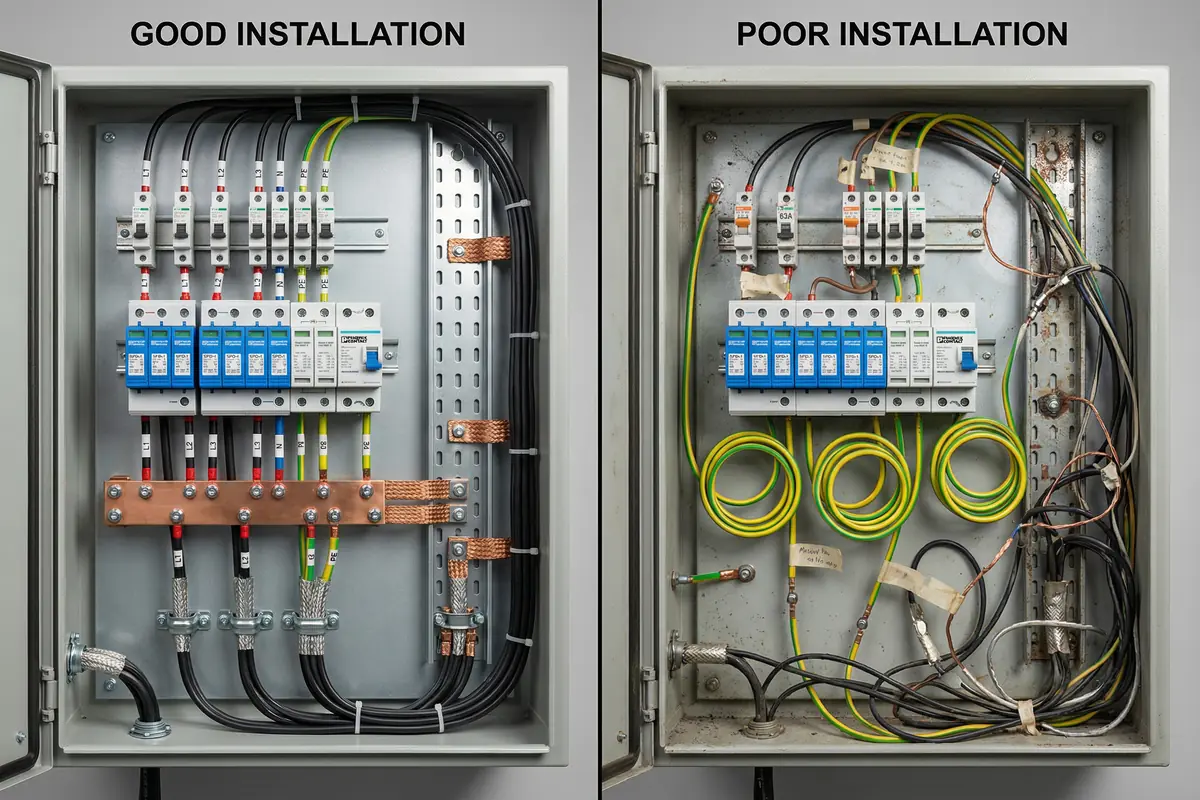
How to Identify Installation Quality On Site
The following checklist provides practical guidance for identifying installation quality during a site visit. Each indicator can be assessed visually or with simple measurement tools, without requiring specialized test equipment. A high-quality installation will pass all ten checks; any failure indicates a deficiency that must be corrected before acceptance.
10.2 Defects and Risk Chain Analysis
Each installation defect creates a specific risk chain that can lead to equipment damage, service outage, or safety hazard. Understanding the risk chain for each defect type helps prioritize corrective actions and communicate the urgency of remediation to stakeholders. The following table presents the most common defect types observed in practice, with their risk chains, severity ratings, and corrective actions.
| Defect Type | Typical Observation | Risk Chain | Severity | Detection Method | Corrective Action |
|---|---|---|---|---|---|
| Long SPD PE leads | Coiled or looped green/yellow leads; lead length > 0.5 m | High lead inductance → higher residual voltage at equipment → equipment damage or latent failure during surge | High | Visual inspection; measure lead length | Relocate SPD closer to MEB; shorten and straighten lead; install local bonding bar if relocation not possible |
| Missing backup fuse/MCB | Blank slot above SPD; wrong rating installed; no protective device | SPD fails short → fault current not cleared → SPD overheats → fire risk | Critical | Panel audit; compare installed device against SPD schedule | Install correct backup device per manufacturer specification; verify rating and type (gG fuse or C-curve MCB) |
| Unbonded tray joints | No bonding straps at tray joints; paint on contact surfaces | Arcing at joints under surge current → EMI injection → port failures; tray sections at different potentials | High | Visual inspection; continuity mapping by tray section | Add flexible bonding jumpers at all joints; remove paint from contact surfaces; verify continuity after installation |
| Shield pigtail terminations | Long drain wire used instead of 360° clamp; pigtail length > 50 mm | Poor high-frequency shield bond → EMI leakage → noise on sensitive circuits; reduced shielding effectiveness | Medium | Visual inspection; compare against shield policy | Replace with 360° clamp terminations at defined bonding bars; update shield policy documentation |
| Copper bypass patch | Copper patch cord crossing zone boundary; unprotected connection bypassing fiber boundary | Direct surge path to core equipment → switch port damage → service outage; security boundary also compromised | High | Patch panel audit; zone boundary verification | Remove copper bypass; restore fiber boundary; lock fiber-only ports; implement change control for patching |
| Corroded outdoor bonds | Rusted lugs; green/white oxidation on copper; loose connections at outdoor bonding points | Impedance rise at corroded connection → reduced bonding effectiveness → repeated small equipment failures; eventual open circuit | High | Visual inspection; periodic torque check; continuity measurement | Replace corroded lugs; clean contact surfaces; apply anti-oxidation compound; use stainless fasteners; re-terminate |
| Missing SPD monitoring | SPD alarm contacts not wired; no NMS mapping; no alarm test record | SPD fails silently → no alarm generated → system continues operating without protection → next surge causes damage | Medium | Alarm contact test; NMS mapping verification | Wire alarm contacts to NMS DI module; test alarm function; document mapping; schedule quarterly alarm tests |
10.3 Quality Control Best Practices
Quality control in lightning protection installation spans five stages: incoming inspection, installation, commissioning, acceptance, and periodic inspection. Each stage has specific activities that must be completed and documented. The following best practices represent the minimum quality control requirements for a compliant installation.
| QC Stage | Activity | Method | Documentation Required |
|---|---|---|---|
| Incoming Inspection | Verify SPD authenticity, ratings, and remote contacts; check busbar/bonding material certificates | Visual inspection; compare against approved vendor list and SPD schedule; check test certificates | Incoming inspection record; certificate copies; non-conformance report if applicable |
| Pre-Install Layout Review | Verify MEB and SPD locations allow short leads; confirm routing plan for separation; confirm shield policy | Drawing review; site walk with installer; measure proposed lead lengths | Layout review sign-off; annotated drawings with proposed lead lengths |
| Installation | Enforce routing rules; use calibrated torque tools; record torque values; apply anti-oxidation compound | Supervised installation; torque wrench with calibration certificate; torque marks applied | Installation checklist; torque records; photo evidence of key connections |
| Commissioning | Continuity mapping; SPD indicator check; alarm integration test; thermal scan under load | Low-ohm meter (4-wire); visual SPD check; NMS alarm simulation; thermal camera | Continuity test report; SPD check record; alarm test log; thermal scan images |
| Acceptance | Full acceptance test per acceptance standard table; verify all items pass; sign off | Per acceptance test plan; independent verification where required | Acceptance test report; as-built drawings; O&M manual handover |
| Periodic Inspection | Quarterly visual; annual comprehensive; post-event focused inspection | Visual inspection checklist; low-ohm spot checks; earth measurement; alarm test | Inspection records; trend data; corrective action register |
Key Best Practices (≥10)
10.4 Acceptance Standards and Test Items
The acceptance test plan defines the specific tests, methods, pass criteria, and evidence requirements for each category of acceptance testing. All items must be completed and documented before the system is accepted. Pass criteria are project-defined examples; actual criteria must be agreed with the project specification and local code requirements.
| Category | Test Item | Method | Pass Criteria (Example) | Evidence Required |
|---|---|---|---|---|
| Functional | SPD installed per schedule (type, location, model) | Physical inspection against SPD schedule | Correct model and location for every SPD in schedule | Annotated photos; signed checklist |
| Electrical | Bonding continuity (racks, trays, shields to MEB) | 4-wire low-ohm meter | Stable low-ohm continuity at all test points (project-defined threshold) | Test report with point-by-point results |
| Electrical | Earth electrode resistance measurement | Fall-of-potential method at MEB test link | Within design target (project-defined, e.g., ≤ 10 Ω) | Test report; test point photo; weather conditions recorded |
| Integration | SPD alarm contact to NMS | Simulate alarm contact; verify NMS receipt | Alarm received, classified, and logged within 60 seconds | NMS screenshot; alarm log export |
| Performance | Ethernet throughput (SPD insertion loss) | iperf3 or equivalent; compare to baseline | Meets specified link rate; no degradation vs. baseline | Test log with timestamps |
| Reliability | UPS path SPD coverage verification | Drawing review + physical inspection | All UPS paths (normal, bypass, generator) covered in SPD schedule | Annotated SLD; inspector sign-off |
| Security | Zone boundary integrity (no copper bypass) | Patch panel audit; port mapping | No copper connections crossing zone boundaries; all inter-zone links are fiber | Port map; patch panel photo |
| Interfaces | Coaxial/RS-485 protection function | Physical inspection + functional communication test | No communication degradation after SPD installation; VSWR/insertion loss within spec | RF test log or comm test record |
| Safety | Backup protective device ratings | Panel audit; compare against SPD schedule | Correct type and rating for every SPD backup device | Panel inspection photos; schedule comparison |
| Documentation | As-built drawings and O&M manual | Document review; spot-check against physical | As-built drawings match physical installation; O&M manual complete and handed over | Signed document handover record |