Chapter 11: Installation & Debugging
11.1 Pre-Installation Requirements
A successful lightning protection installation begins well before the first component is mounted. Pre-installation activities ensure that the environment is ready, the team is qualified, the materials are verified, and the risks are understood. The following requirements must be met before installation work begins. Any unresolved item should be escalated and resolved before proceeding.
Environment, Space, Power, and Network Readiness
| Category | Requirement | Verification Method |
|---|---|---|
| Environment | Room temperature, humidity, and cleanliness within specification; no active water leaks or condensation | Visual inspection; environmental sensor check |
| Space | MEB location allows short bonding leads to all racks and SPDs; SPD panel locations allow short PE leads to MEB; maintenance access corridors clear | Layout review; measure proposed lead lengths |
| Power | Panel space available for SPDs and backup devices; UPS topology documented including bypass and generator paths | Panel survey; single-line diagram review |
| Network | Fiber boundaries defined and documented; patch panel locations confirmed; NMS DI module capacity verified for SPD alarm inputs | Network diagram review; NMS capacity check |
People, Tools, and Materials
| Category | Requirement |
|---|---|
| People | Qualified electrical engineer responsible for SPD and bonding installation; safety officer for lockout/tagout; network engineer for fiber boundary and NMS integration |
| Tools | Calibrated torque wrench (with certificate); low-ohm meter (4-wire Kelvin method); thermal camera; cable labeling machine; fall-of-potential earth tester; PPE (safety glasses, insulated gloves, hard hat) |
| Materials | All SPDs verified against approved vendor list and SPD schedule; bonding busbars and conductors with material certificates; anti-oxidation compound; heat-shrink label sleeves; stainless fasteners for outdoor bonds; spare SPD cartridges |
Pre-Installation Risk Prechecks (≥12)
11.2 Installation Requirements
The following installation demonstration photographs illustrate the key requirements for each major installation task. Each photograph is accompanied by a description of the critical installation details that must be present for the installation to be considered compliant. These requirements apply to all installations regardless of scale.
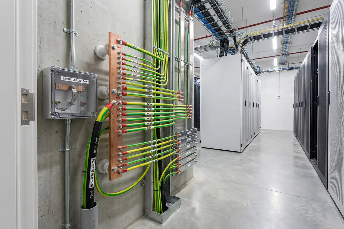
Wall-mounted copper MEB on insulated standoffs near the room entrance. Labeled terminals with unique IDs on all conductors. Heavy bonding strap to main earthing conductor. Earth test link box with disconnecting link mounted adjacent. Clear service access corridor maintained in front of the MEB.
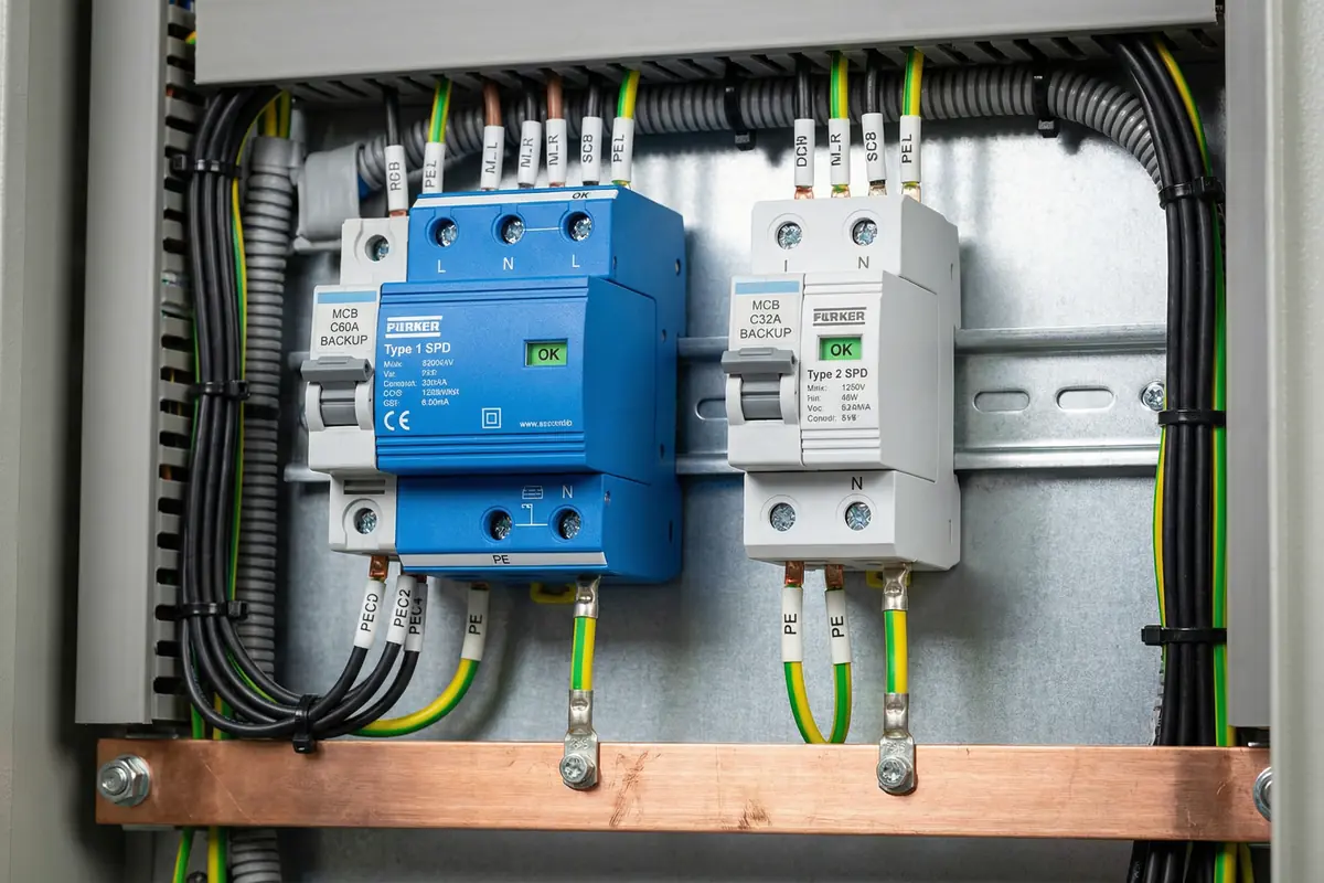
Type 1 (blue) and Type 2 (white) SPDs installed on DIN-rail adjacent to busbars. Short straight PE leads (under 0.5 m) connecting directly to copper bonding busbar at panel base. Backup MCBs labeled with ratings. Wiring dressed neatly. SPD status indicator windows showing green (OK) status.
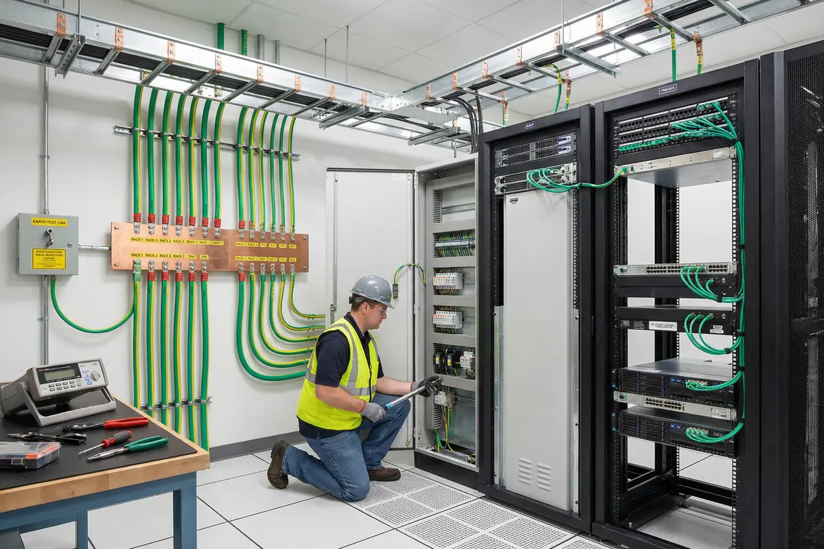
Complete installation showing: copper MEB with labeled terminals and bonding conductors to racks, server racks with rack bonding bars and short jumpers to equipment chassis, overhead cable tray with bonding straps at every joint, SPD panel in electrical cabinet, fiber patch panel at top of rack for inter-zone connections, earth test link box on wall, all conductors labeled.
Correct Installation Steps
Common Installation Errors and Consequences (≥8)
| Error | Consequence | Prevention |
|---|---|---|
| MEB placed far from entry | Long SPD leads → higher residual voltage at equipment → reduced protection effectiveness | Plan MEB location before construction; verify lead lengths in layout review |
| SPD installed without backup device | SPD fails short → fault current not cleared → overheating → fire risk | Enforce backup device requirement in installation checklist; verify before energization |
| Signal SPD grounded to rack screw | Poor reference and potential ground loops → EMI issues → communication errors | Require all signal SPDs to bond to designated bonding bar; prohibit rack screw grounding |
| Tray joints unbonded | Arcing at joints under surge current → EMI injection → port failures; tray sections at different potentials | Include tray bonding in installation checklist; verify continuity before acceptance |
| Shield pigtails used everywhere | Poor high-frequency shielding → EMC issues → noise on sensitive circuits | Enforce 360° clamp policy; include shield termination in installation training |
| Copper bypass patch added later | Direct surge path to core equipment → switch port damage → service outage | Physical locks on fiber-only ports; change control for patching; periodic patch audit |
| Outdoor bonds not corrosion-protected | Corrosion → impedance rise → reduced bonding effectiveness → repeated equipment failures | Require anti-oxidation compound and stainless fasteners for all outdoor bonds; include in inspection schedule |
| UPS bypass path omitted from SPD schedule | Surge bypasses UPS protection via unprotected bypass path → equipment damage during UPS maintenance or transfer | Include bypass path in SPD schedule; verify in acceptance test |
11.3 Construction Norms
Construction norms define the workmanship standards that must be maintained throughout the installation. These norms cover routing, fixing, labeling, grounding, spacing, heat management, and physical protection. Compliance with these norms is verified during installation inspection and at acceptance testing.
| Category | Norm | Checkpoint |
|---|---|---|
| Routing | Strong/weak separation maintained; power and data cables cross at right angles where unavoidable; no parallel runs of power and sensitive data cables within separation distance; avoid routing near down conductors | Visual inspection; measure separation distances at critical points |
| Fixing | Strain relief on all conductors at entry points; no sharp bends on bonding conductors; bonding straps protected from mechanical damage; cable ties not over-tightened on bonding conductors | Visual inspection; check for kinks or sharp bends |
| Labeling | Unique IDs for all SPDs, bonding conductors, test points, and penetrations; heat-shrink labels used; labels legible and durable; as-built drawings updated to match labels | Spot-check labels against as-built drawings |
| Grounding | Paint removed at all bonding contact surfaces; correct lug type and size for conductor cross-section; torque applied and marked; anti-oxidation compound applied before lug installation | Visual inspection; torque mark verification; low-ohm test |
| Spacing | Defined separation maintained between power and data cables; sensitive cables kept away from down conductors; SPD PE leads not routed parallel to incoming supply conductors | Measure separation at closest points; verify routing plan compliance |
| Heat | Panel ventilation maintained; SPDs not bundled with other heat-generating equipment; no cable bundles obstructing SPD ventilation slots; thermal scan performed after energization | Visual inspection; thermal camera scan under load |
| Protection | All penetrations sealed with fire-rated compound after cable installation; outdoor entries use IP-rated glands; outdoor bonding connections protected from moisture ingress | Visual inspection; verify gland IP ratings; check penetration sealing |
Construction Checkpoints
- Continuity mapping: verify all racks, trays, and shield bars to MEB
- Visual lead length check: verify all SPD PE leads are short and straight
- Backup device verification: confirm correct type and rating for every SPD
- Penetration register: confirm all entries are registered and protected
- Zone boundary check: confirm no copper connections cross zone boundaries
- SPD indicator check: verify all SPD status windows show OK (green)
- Alarm integration test: simulate each SPD alarm contact and verify NMS receipt
- Thermal scan: inspect all panels and major bonding connections under load
- Functional test: verify network throughput and PoE delivery meet specification
- Earth measurement: measure earth electrode resistance at test link box
11.4 Debugging Methods
Debugging a lightning protection and network system requires a systematic approach that begins with baseline documentation and proceeds through zone verification, SPD validation, bonding validation, and functional testing. The following process and issue-solving ideas provide a structured framework for identifying and resolving installation issues.
Debugging Process
Issue-Solving Ideas (≥5)
| Symptom | Investigation Steps | Resolution |
|---|---|---|
| Frequent port CRC errors | Inspect shield termination quality; check routing separation from power conductors; verify no parallel runs near down conductors | Improve shield terminations to 360° clamps; reroute cables to maintain separation; add bonding straps to tray sections near problem ports |
| PoE drops intermittently | Confirm PoE SPD compatibility with PoE class; check power budget; verify bonding reference for signal SPD | Replace incompatible PoE SPD; adjust power budget; bond signal SPD to designated bonding bar instead of rack screw |
| SPD alarms nuisance tripping | Verify SPD coordination (Up values in cascade); check backup device ratings; verify earthing reference quality | Review SPD cascade coordination; replace incorrectly rated backup devices; improve earthing reference if resistance is high |
| UPS shows unexplained transfers | Correlate UPS transfer timestamps with storm events; verify bypass path protection; check bonding of UPS chassis | Add or repair SPDs on bypass path; improve bonding; add storm correlation dashboard to NMS |
| Outdoor device failures repeat | Inspect corrosion at outdoor bonding points; verify fiber conversion is in place; check gland sealing | Enforce fiber conversion for all outdoor links; replace corroded bonds; seal glands; improve corrosion protection |
Rollback Policy
Any change that introduces a copper bypass across a zone boundary must be rolled back immediately, regardless of the reason for the change. Troubleshooting activities that require temporary copper connections must be documented, time-limited, and removed as soon as the troubleshooting is complete. Keep spare pre-configured switches and media converters available for rapid swap during fault isolation, so that fiber boundaries can be maintained even during equipment replacement activities.
11.5 Rack, Stack, and Cabling Requirements
Rack layout and cabling practices directly affect both the maintainability and the reliability of the lightning protection system. A well-organized rack makes SPD lead routing straightforward, bonding bar access easy, and fiber boundary maintenance practical. The following requirements apply to all rack installations in the system.
Cabling Best Practices for Maintainability and Reliability
| Aspect | Requirement | Rationale |
|---|---|---|
| Service loops | Minimum 300 mm service loop on all patch cords; do not use exact-length cords | Allows equipment to be pulled forward for maintenance without disconnecting cables; prevents cable strain |
| Tight bundling near SPDs | Do not bundle cables tightly around or near SPD PE leads | Tight bundling traps heat around SPDs; also increases inductive coupling between SPD leads and signal cables |
| Fiber boundary labeling | Label fiber patch panel ports "ZONE BOUNDARY — FIBER ONLY"; use physical port locks on unused ports | Prevents accidental or unauthorized copper bypass; makes boundary visible to all personnel |
| Bonding bar access | Rack bonding bar must be accessible without removing other equipment; route jumpers to allow individual removal | Enables periodic torque checks and continuity measurements without service disruption |
| Cable tray bonding | Verify tray bonding strap is not obstructed by cable bundles; maintain access for inspection | Allows periodic torque verification and visual inspection of bonding straps |