Chapter 2: Design Methods
2.1 Core Concepts and Definitions
Lightning protection for network and data systems rests on a set of fundamental concepts that distinguish it from simple "add an SPD" thinking. These concepts must be understood by all stakeholders — designers, installers, and O&M staff — to ensure that design decisions are made correctly and that the installed system performs as intended.
| Concept | Definition | Design Implication |
|---|---|---|
| Ground Potential Rise (GPR) | The rise in earth potential at a grounding point relative to remote earth during a fault or lightning event | All metallic structures must be bonded to the same reference to prevent dangerous potential differences between equipment |
| Equipotential Bonding | Connecting all metallic parts to a common reference to minimize potential differences | MEB must connect all racks, trays, panels, shields, and metallic services; continuity must be verified |
| SPD Coordination | Staged protection where each downstream SPD handles only the residual energy after the upstream stage | Type 1 → Type 2 → Type 3 cascade; each stage must be matched in Up and energy handling |
| Impulse Inductance | The inductive voltage drop across a conductor during fast-rising surge current (V = L × di/dt) | SPD PE leads must be short and straight; coiled or long leads negate the SPD clamping effect |
| Zone Concept (LPZ) | Dividing a facility into zones with decreasing lightning threat levels from outside to inside | Fiber boundaries at zone transitions; SPDs at zone entry points; controlled penetrations |
| Fiber Boundary | Using optical fiber to break the conductive path between zones, eliminating surge propagation | Preferred for all inter-zone and outdoor links; media converters need power SPD protection |
| Residual Voltage (Up) | The maximum voltage across an SPD during a defined test impulse | Up must be below equipment withstand voltage; coordination requires Up(downstream) < Up(upstream) |
| Penetration Register | A documented list of all conductors entering the protected zone | Every external conductor must be registered, protected, and routed through the entrance facility |
The Surge Current Path Principle
The most important design principle is that surge current must be given a deliberate, low-impedance path to earth. If no such path is provided, the current will find its own path — through equipment chassis, signal cables, or structural steel — causing damage along the way. The design task is to create and maintain the intended surge path (external line → SPD → short lead → MEB → earth electrode) while ensuring that equipment and signal cables are not in that path.
Key Rule: Every metallic conductor entering the protected space is a potential surge entry point. Every unprotected entry is a design gap. The penetration register is the tool that ensures no entry is overlooked.
2.2 Common Failure Modes and Root Causes
Understanding common failure modes is essential for both design review and post-incident analysis. The majority of lightning-related equipment failures in network facilities can be traced to a small set of recurring installation and design errors. The following analysis covers the most critical failure modes with their root causes, mechanisms, and recommended corrective actions.
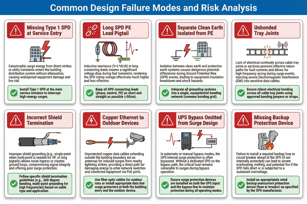
| Failure Mode | Root Cause | Mechanism | Recommendation |
|---|---|---|---|
| Missing Type 1 SPD at service entry | Design omission or cost cutting | Full surge energy enters building distribution; downstream SPDs overloaded | Install Type 1 at MDB/service entry; verify class and upstream protection |
| Long, coiled SPD PE lead | SPD installed far from bonding bar; lead coiled for neatness | Inductive rise (V=L×di/dt) makes clamp voltage ineffective; residual voltage at equipment remains high | Relocate SPD or install local bonding bar tied to MEB with wide strap; target lead length < 0.5 m straight |
| Separate "clean earth" isolated from PE | Misconception that IT equipment needs a separate "quiet" earth | Dangerous potential difference between clean earth and PE during GPR; equipment insulation breakdown | Use equipotential bonding; if functional earth needed, bond via defined impedance but never isolate |
| Unbonded cable tray joints | Tray installed without bonding jumpers; paint not removed at contact | Arcing at joints during surge; EMI injection into adjacent cables | Bond each joint with flexible jumper; remove paint at contact; verify continuity |
| Shield terminated incorrectly | Random single-end bonding; pigtail drain wire used | Noise ingress or ground-loop current depending on frequency and topology | Define shield policy per cable type and zone; use 360° clamps for HF applications |
| Copper Ethernet to outdoor devices | Cost or convenience; fiber not specified | Surges enter via Ethernet/PoE pairs; switch ports damaged | Convert to fiber at outdoor boundary; if copper required, install PoE-compatible Ethernet SPDs at both ends |
| UPS bypass path omitted from surge design | SPD schedule covers normal path only; bypass overlooked | During bypass operation, surge bypasses entire SPD chain; equipment unprotected | Include all power paths (normal/bypass/generator/ATS) in SPD schedule; verify with SLD |
| Missing backup protection device | SPD installed without fuse or MCB; or wrong rating used | Follow-current causes SPD overheating and potential fire | Select backup device per SPD manufacturer specification; document in SLD and label panel |
2.3 Core Design and Selection Logic
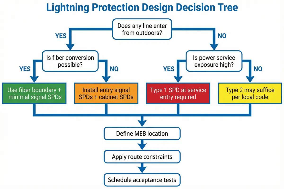
The design process follows a structured seven-step decision sequence. Each step builds on the previous, and the outputs of each step feed into the next. Skipping steps or performing them out of order leads to design gaps that are difficult to detect and expensive to correct. The decision tree below illustrates the key branching logic for the most critical decisions.
Seven-Step Design Process
- Identify boundaries: Determine the site boundary (outdoor exposure), all entry points (power, telecom, coax, metallic pipes), and the zone layout (External/Entrance, DMZ, Core). This step produces the penetration register and zone boundary map.
- Define surge exposure class: Assess whether overhead lines, nearby towers, long buried cables, or coastal corrosion are present. Determine whether Type 1 SPD is mandatory at the service entry based on exposure and local code requirements.
- Choose earthing and bonding topology: Select MEB location(s), bonding conductor routes, rack bonding method, and tray bonding spacing. Determine test point placement for periodic measurement.
- Decide copper vs. fiber strategy: Any link crossing a zone boundary or going outdoors should use fiber as the first choice. Copper is acceptable only within controlled zones or for short indoor runs where surge exposure is low.
- SPD coordination: For power: Type 1 → Type 2 → Type 3, including UPS input/output/bypass and generator/ATS paths. For signal: entry SPD or isolation at zone boundary, cabinet SPD near equipment, with correct earthing reference for each.
- Shielding and routing: Define separation distances, crossing rules, penetration treatment, and shield termination policy for each cable type and zone. Document in cable routing drawings.
- Monitoring and acceptance: Specify SPD remote contacts and their integration with NMS/BMS. Define the testing plan (continuity, earth measurement, SPD alarm test) and the O&M schedule (quarterly visual, annual test, post-event inspection).
Common Mistake: Designing SPD placement before confirming MEB location. The MEB location must be determined first (Step 3), because it constrains where SPDs can be placed to achieve short lead lengths (Step 5). Reversing this order often results in SPDs that cannot meet the lead length requirement.
2.4 Key Design Dimensions
A complete lightning protection design must address multiple quality dimensions simultaneously. Focusing on a single dimension — such as SPD ratings — while neglecting others leads to systems that pass acceptance tests but fail in service. The following dimensions must each be explicitly addressed in the design documentation.
| Dimension | Key Considerations | Common Shortfall | Design Response |
|---|---|---|---|
| Performance | Signal SPDs must not degrade bandwidth; shielding must not cause packet errors; routing must avoid EMI hotspots | SPD selected for surge rating only; bandwidth not verified | Test throughput and PoE delivery after installation; verify Ethernet category compliance |
| Stability & Reliability | Coordinated protection, redundant paths (fiber rings), SPD health monitoring, robust bonding | Single-path protection with no monitoring; bonding not verified after installation | Design redundant fiber paths; integrate SPD alarms; perform continuity mapping at acceptance |
| Maintainability | Accessible MEB and SPDs; labeled conductors; replaceable modules; test points | SPDs installed in inaccessible locations; no labeling; no test points | Specify accessibility in layout drawings; require labeling in installation spec; include test links |
| Compatibility & Expansion | Spare terminals on MEB; spare SPD slots; room for future carriers/links; standard interfaces | MEB fully populated at commissioning; no room for future SPDs | Specify minimum spare capacity (e.g., 20% spare terminals); use modular SPD systems |
| Life-Cycle Cost (LCC) | Invest in correct zoning and fiber boundaries to reduce repeated lightning repairs | Low initial cost but high O&M cost from repeated port failures | Calculate LCC including expected failure costs; fiber boundary typically reduces total cost |
| Energy & Environment | Avoid unnecessary conversion losses; ensure corrosion-resistant materials | Non-rated materials in outdoor bonds; corrosion causes repeated failures | Specify material grades for outdoor/corrosive environments; include anti-oxidation compound |
| Compliance & Certification | Align with local electrical code, SPD standards, and cabling standards; document as-built evidence | Design meets intent but lacks documented evidence for inspection | Maintain test reports, photos, and as-built drawings; reference applicable standards in design documents |
Recommended Indicator Ranges
The following table provides recommended ranges and targets for key measurable parameters. These values are guidance based on engineering principles and common practice; project-specific values must be confirmed against the applicable standards and site conditions.
| Parameter | Recommended Range/Target | Rationale |
|---|---|---|
| SPD PE lead length (local) | As short as practical; target ≤ 0.5 m straight | Reduce inductive residual voltage; impulse inductance scales with lead length |
| Bonding conductor style | Wide strap or short large CSA conductor | Impulse current favors low inductance; wide straps have lower inductance than round conductors |
| Tray continuity | Continuous; bond across all joints | Avoid arcing points; maintain EMC return path |
| Equipotential continuity (room bonds) | Stable low-ohmic continuity (project-defined) | Use method suitable for low-ohm measurement; 4-wire preferred |
| Fiber boundary usage | Prefer for all outdoor and zone-crossing links | Break surge path; eliminate signal SPD requirement for that link |
| Entry governance | 100% of external copper through demarc | No hidden bypass; penetration register must be complete |
| SPD monitoring coverage | 100% of critical SPDs with remote contacts | Avoid silent exposure after SPD degradation |
| Inspection interval | Quarterly visual; annual test; post-event inspection | Practical O&M loop that catches degradation before next storm season |