Chapter 3: Scenarios & Selection
Eight Application Scenarios with Real-World Installations and Key Technical Specifications
This chapter presents eight representative application scenarios for lightning protection and earthing in network and data systems. Each scenario describes the site type, key protection challenges, recommended design approach, and critical technical parameters. These scenarios serve as reference cases for design engineers selecting the appropriate protection strategy for their specific site conditions.
1
Enterprise Data Center — Multi-Row Server Room
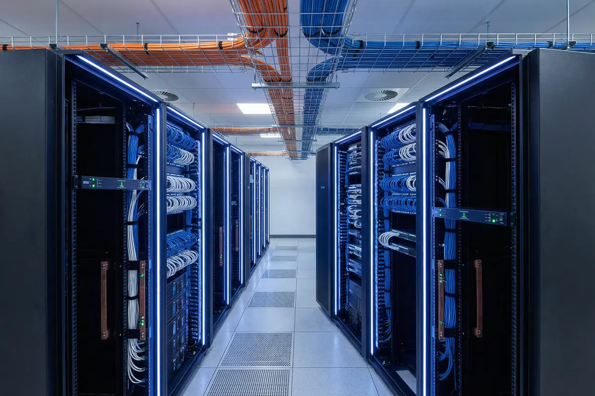
Figure 3.1: Enterprise data center with separated power (orange) and data (blue) cable trays, rack bonding bars, and SPD panels in a cold/hot aisle arrangement.
Enterprise data centers with multiple rows of server racks represent the highest-density and highest-criticality application for lightning protection. The primary challenges are maintaining equipotential bonding across all racks in a large room, coordinating power SPDs through the full distribution chain (utility → UPS → PDU → rack PDU), and managing the large number of signal line entries from external networks. The cold/hot aisle arrangement creates specific cable routing constraints that must be addressed in the bonding and separation design.
| Protection Element | Specification | Notes |
|---|---|---|
| Power SPD cascade | Type 1 at MDB + Type 2 at UPS input/output + Type 3 at rack PDU | Include UPS bypass and generator/ATS paths |
| Rack bonding | Each rack bonded to MEB via bonding conductor; racks in a row cross-bonded | Bonding bar on each rack; labeled test points |
| Cable tray bonding | Bonding jumper at every tray joint; continuity verified | Separate trays for power and data; min. separation per IEC 61000-5-2 |
| Signal line entry | All external copper through entrance facility SPDs; fiber preferred for inter-building | Penetration register maintained; no uncontrolled entries |
| Monitoring | 100% of critical SPDs with remote contacts; integrated with DCIM/BMS | SPD alarm events correlated with network performance data |
SPD PE Lead Length
≤ 0.5 m straight
Rack Bonding Coverage
100% of racks
Power/Data Separation
Separate trays
External Entry Governance
100% registered
SPD Monitoring Coverage
100% critical SPDs
Inspection Interval
Quarterly visual / Annual test
2
MDF / IDF Room — Main Distribution Frame
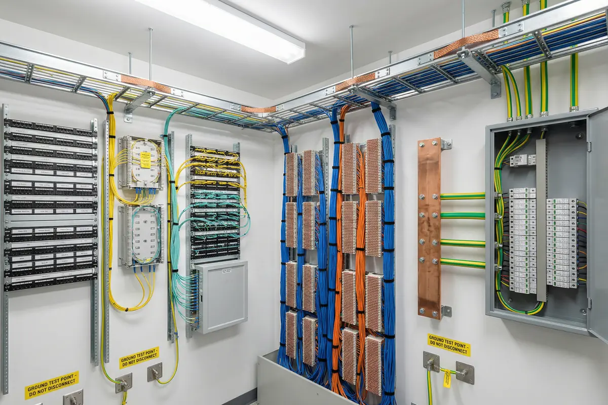
Figure 3.2: MDF room with copper bonding busbar, multiple green/yellow bonding conductors, patch panels, fiber distribution, and labeled ground test points.
The MDF is the primary network demarc point where external carrier circuits enter the building. It is the highest-risk location for surge entry via telecom lines and must be treated as the primary signal line entry governance point. The MEB should be located in or adjacent to the MDF to minimize SPD lead lengths. All carrier circuits — copper DSL, T1/E1, analog POTS, coax — must pass through SPDs before connecting to internal distribution equipment. The MDF bonding bar serves as the local bonding reference for all signal SPDs in the room.
| Protection Element | Specification | Notes |
|---|---|---|
| MEB location | In or adjacent to MDF; accessible for testing | Short bonding conductor to building earth electrode |
| Carrier circuit SPDs | SPD at each external copper circuit entry; fiber preferred where available | DSL, T1/E1, POTS, coax — all must be registered and protected |
| Bonding bar | Copper busbar mounted on wall; labeled terminals; test link to MEB | All SPD earth leads ≤ 0.5 m to bonding bar |
| Test points | Labeled test points at MEB and bonding bar; accessible without disconnecting | Annual earth resistance measurement; quarterly visual |
| Penetration register | Complete register of all external circuits; updated when circuits added/removed | No unregistered entries; sealed penetrations |
SPD Lead to Bonding Bar
≤ 0.5 m
External Circuit Coverage
100% registered & protected
Bonding Bar Terminals
20% spare capacity
Test Point Accessibility
All accessible without disconnect
Fiber Boundary Usage
Preferred for all inter-building
Earth Resistance Test
Annual measurement
3
Outdoor Network Cabinet — Campus / Industrial Site
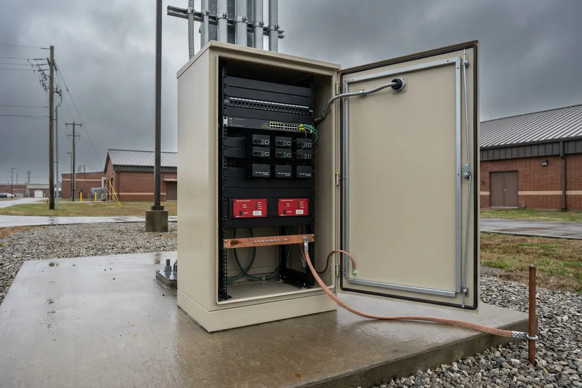
Figure 3.3: Outdoor weatherproof network cabinet on concrete pad with internal bonding bar, SPD modules, fiber media converters, and external grounding conductor to earth rod.
Outdoor network cabinets represent the highest lightning exposure scenario for network equipment. Located in open areas, often near towers, poles, or elevated structures, these cabinets are directly exposed to induced surges from nearby strikes. The cabinet itself must be bonded to a local earth electrode, and all power and signal lines entering the cabinet must be protected by SPDs. Fiber conversion at the cabinet boundary eliminates the copper surge path from the cabinet back to the building. The cabinet bonding bar connects the SPD earth leads, the cabinet frame, and the external earth conductor to a common reference.
| Protection Element | Specification | Notes |
|---|---|---|
| Cabinet earth electrode | Dedicated earth rod at cabinet; bonded to building earth via bonding conductor | Earth resistance measured; soil resistivity considered |
| Power SPD | Type 2 minimum at cabinet power entry; Type 1 if overhead supply | Weatherproof SPD rated for outdoor ambient temperature range |
| Signal line strategy | Fiber conversion at cabinet boundary preferred; if copper required, SPDs at both ends | Fiber media converter protected by power SPD; no unprotected copper to building |
| Cabinet bonding | Cabinet frame bonded to earth; door bonded to frame via flexible strap | Corrosion-resistant bonding materials for outdoor environment |
| Environmental rating | IP55 minimum for cabinet; SPDs rated for outdoor temperature and humidity | Anti-corrosion treatment for all bonding conductors and connections |
Cabinet Earth Resistance
Per site assessment
Fiber Boundary
Preferred at cabinet
Cabinet IP Rating
IP55 minimum
SPD Temperature Range
Rated for site ambient
Door Bonding
Flexible strap to frame
Inspection Interval
Quarterly visual; post-storm
4
Industrial Control Room — SCADA / PLC Network
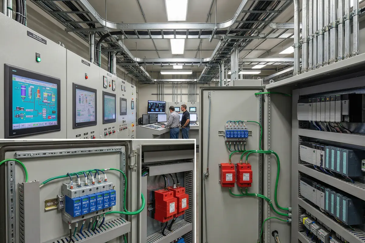
Figure 3.4: Industrial SCADA/PLC control room with HMI screens, DIN-rail mounted RS-485 SPDs, power SPDs in distribution panels, and bonding conductors to cabinet frames.
Industrial control rooms with SCADA and PLC systems present unique lightning protection challenges due to the mix of long-run RS-485 field device cables, analog signal loops, and Ethernet-connected HMI/SCADA systems. RS-485 cables running to field devices in exposed locations are particularly vulnerable to induced surges. The DIN-rail mounted RS-485 SPDs must be compatible with the baud rate and biasing requirements of the specific control system. Power SPDs must be selected for the industrial supply voltage and must not interfere with the UPS or generator transfer logic.
| Protection Element | Specification | Notes |
|---|---|---|
| RS-485 SPDs | DIN-rail SPD at each RS-485 field cable entry; compatible with baud rate and biasing | Verify insertion loss and biasing compatibility with PLC vendor |
| Analog signal SPDs | SPD at entry of each 4-20mA or 0-10V analog loop from field | Maintain signal accuracy; low insertion resistance |
| Power SPD | Type 2 at control panel power entry; Type 3 at sensitive PLC/HMI power supply | Coordinate with UPS/generator transfer logic; avoid nuisance tripping |
| Cabinet bonding | All cabinet frames bonded to plant earth; DIN rail bonded to cabinet frame | Verify continuity through DIN rail to cabinet frame to earth |
| Field cable routing | Separate conduits for power and signal; metal conduit bonded at both ends | Avoid running signal cables parallel to power cables in field |
RS-485 SPD Compatibility
Baud rate & biasing verified
Analog Signal Accuracy
SPD insertion resistance < 1 Ω
Cabinet Frame Bonding
100% of cabinets bonded
DIN Rail Continuity
Verified at acceptance
Power/Signal Separation
Separate conduits in field
UPS/Generator Coordination
SPDs on all power paths
5
Telecom Equipment Shelter / POP
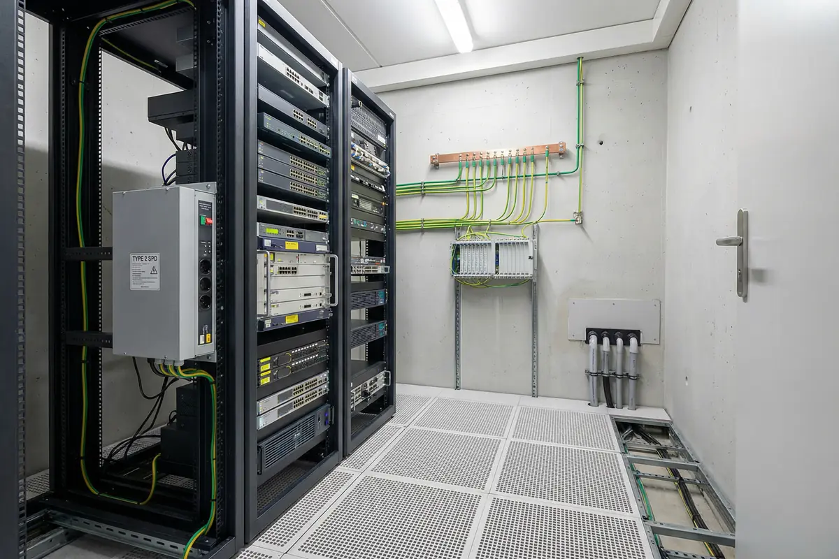
Figure 3.5: Telecom POP shelter with Type 2 SPD at power entry, copper bonding busbar on wall, fiber distribution frame, and cable entry through sealed conduits in raised floor.
Telecom equipment shelters and Points of Presence (POPs) are compact, high-density facilities that often serve as aggregation points for multiple external circuits. They may be located in remote or semi-outdoor environments with high lightning exposure. The compact size means that the MEB can be located close to all equipment, enabling short SPD lead lengths. However, the high density of external circuit entries — carrier fiber, copper pairs, coax feeders, power — requires a rigorous penetration register and systematic SPD application. The raised floor or cable entry system must maintain zone integrity.
| Protection Element | Specification | Notes |
|---|---|---|
| MEB location | Central bonding bar on wall; accessible; short leads to all equipment | All external circuit SPDs bonded to this bar; ≤ 0.5 m leads |
| External circuit SPDs | SPD at each copper circuit entry; fiber preferred; coax SPD for feeder entries | Complete penetration register; no unregistered entries |
| Power SPD | Type 2 at shelter power entry; Type 3 at sensitive equipment power supplies | Coordinate with any generator or UPS in the shelter |
| Cable entry system | Raised floor or wall entry with sealed penetrations; bonded metallic conduits | Maintain zone integrity; no gaps around cable bundles |
| Earth electrode | Dedicated earth electrode at shelter; bonded to building/site earth network | Earth resistance measured; documented in shelter records |
SPD Lead Length
≤ 0.5 m to bonding bar
External Circuit Coverage
100% registered & protected
Penetration Sealing
All penetrations sealed
Earth Electrode
Dedicated; measured annually
Fiber Boundary
Preferred for all inter-site
Spare Terminal Capacity
≥ 20% spare on bonding bar
6
Campus Building IDF — Floor Distribution Room
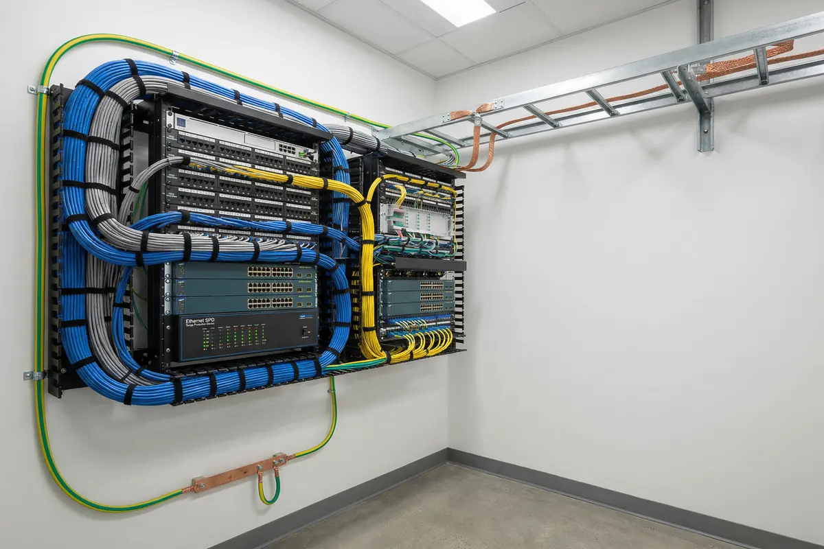
Figure 3.6: Campus IDF closet with wall-mounted rack, patch panels, Ethernet SPD panel, copper bonding bar, and green/yellow grounding conductors to building earth.
Campus building IDF closets serve as floor-level distribution points for structured cabling systems. They receive fiber from the MDF and distribute copper Ethernet to workstations, IP phones, and access points. The primary lightning risk is from copper Ethernet cables running to outdoor devices — access points on rooftops, cameras on building exteriors, or inter-building copper links. These outdoor copper runs must be treated as external lines and protected accordingly. The IDF bonding bar provides the local reference for Ethernet SPDs protecting outdoor device ports.
| Protection Element | Specification | Notes |
|---|---|---|
| Outdoor device strategy | Fiber conversion preferred for rooftop/exterior devices; if copper, PoE-compatible Ethernet SPDs at both ends | Identify all outdoor copper runs in penetration register |
| IDF bonding bar | Small copper bonding bar in IDF; bonded to building earth via green/yellow conductor | All Ethernet SPD earth leads ≤ 0.5 m to bonding bar |
| Inter-building links | Fiber only for inter-building connections; no unprotected copper between buildings | Existing copper inter-building links must be converted or protected |
| PoE SPD compatibility | Ethernet SPDs must support PoE standard (IEEE 802.3af/at/bt) without power loss | Verify PoE budget after SPD insertion; test PoE delivery |
| Rack/tray bonding | Rack bonded to IDF bonding bar; cable tray bonded at joints | Continuity verified at acceptance |
Outdoor Copper Identification
100% registered
PoE SPD Compatibility
IEEE 802.3af/at/bt verified
Inter-Building Links
Fiber only
SPD Lead Length
≤ 0.5 m to bonding bar
Rack Bonding
Rack bonded to IDF bar
Inspection Interval
Quarterly visual
7
Security & Surveillance System — NVR / CCTV
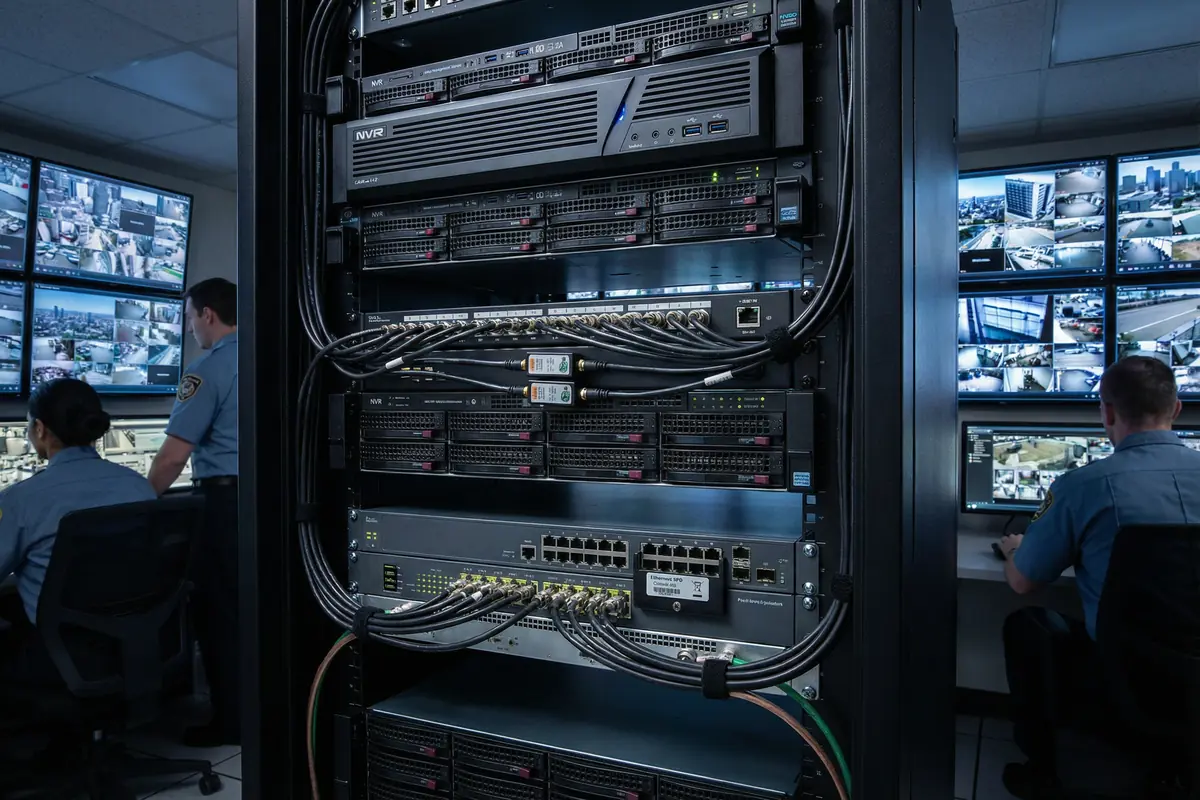
Figure 3.7: Security operations center with NVR rack, coaxial SPDs on coax connections, PoE switch with Ethernet SPD panel, bonding conductors, and multiple camera feeds on monitors.
Security and surveillance systems are particularly vulnerable to lightning damage because cameras are typically mounted outdoors in exposed locations, connected back to NVRs via copper coax or Ethernet cables. Each outdoor camera represents a direct surge entry point. Coaxial SPDs must be installed at the NVR end of each coax run, and PoE-compatible Ethernet SPDs must be installed for IP camera connections. The high number of camera ports in large systems requires a systematic approach to SPD installation, with all SPD earth leads bonded to a common bar connected to the building earth.
| Protection Element | Specification | Notes |
|---|---|---|
| Coax SPDs | Coaxial SPD at NVR end of each outdoor coax run; frequency range compatible with video signal | Verify insertion loss at operating frequency; maintain video quality |
| IP camera SPDs | PoE-compatible Ethernet SPD at switch port for each outdoor IP camera | SPD at both switch end and camera end for long runs; PoE budget verified |
| NVR/server bonding | NVR rack bonded to room bonding bar; bonding bar connected to building earth | Short bonding leads; labeled connections |
| Power SPD | Type 2 at NVR room power entry; Type 3 at NVR/server power supply inputs | Coordinate with UPS if present |
| Fiber conversion | Fiber preferred for long outdoor camera runs; media converter at camera end protected by local SPD | Eliminates copper surge path; preferred for new installations |
Coax SPD Coverage
100% outdoor coax runs
IP Camera SPD Coverage
100% outdoor IP cameras
Coax SPD Insertion Loss
Per video signal spec
PoE Compatibility
IEEE 802.3af/at verified
Fiber Conversion
Preferred for long runs
NVR Rack Bonding
Bonded to building earth
8
Edge Computing Node — Remote / Industrial Site
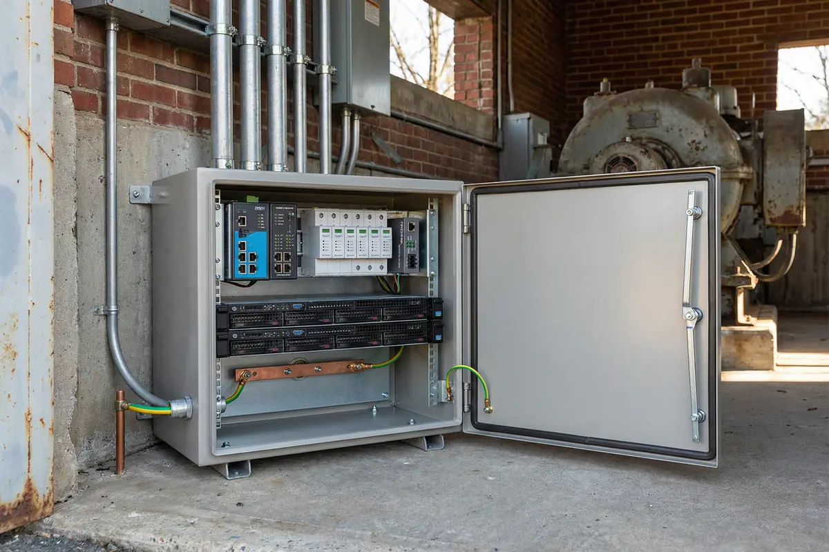
Figure 3.8: Edge computing node in ruggedized enclosure at industrial site with edge servers, industrial switch, SPD modules, fiber media converter, bonding bar, and external grounding conductor.
Edge computing nodes deployed at remote or industrial sites face the combined challenges of high lightning exposure, limited physical access for maintenance, and the need for high availability. The compact enclosure must incorporate all protection elements — earth electrode, bonding bar, power SPD, signal SPDs, and fiber boundary — in a small footprint. Remote monitoring of SPD health is particularly important at these sites because physical inspection may be infrequent. The design must minimize the need for on-site maintenance while ensuring that protection integrity can be verified remotely.
| Protection Element | Specification | Notes |
|---|---|---|
| Earth electrode | Dedicated earth rod at node; bonded to site earth network if available | Earth resistance documented; accessible test link |
| Compact bonding bar | Small copper bonding bar inside enclosure; all SPD leads ≤ 0.5 m | Bonded to enclosure frame and external earth conductor |
| Power SPD | Type 2 at enclosure power entry; compact DIN-rail format for space efficiency | Rated for site ambient temperature; remote alarm contact |
| Signal line strategy | Fiber boundary at enclosure; fiber media converter protected by power SPD | No unprotected copper connections to remote equipment |
| Remote monitoring | SPD remote alarm contacts connected to edge management system; email/SMS alert on SPD fault | Critical for sites with infrequent physical access |
Earth Electrode
Dedicated; documented
Fiber Boundary
At enclosure boundary
SPD Lead Length
≤ 0.5 m in enclosure
Remote Monitoring
SPD alarm to management system
SPD Temperature Rating
Rated for site ambient
Inspection Interval
Remote quarterly; on-site annual
3.9 Scenario Selection Guide
The following table provides a quick reference for selecting the appropriate protection strategy based on site type and key characteristics. Use this table as a starting point for design, then refer to the detailed scenario description for specific requirements.
| Site Type | Key Risk | Primary Strategy | Critical SPD Types | Reference Scenario |
|---|---|---|---|---|
| Enterprise data center | Large-scale equipment loss; high criticality | Full cascade + comprehensive bonding + monitoring | Type 1/2/3 power + entry signal SPDs | Scenario 1 |
| MDF/demarc room | Multiple external carrier circuit entries | Rigorous entry governance + MEB at demarc | Telecom SPDs + power SPDs | Scenario 2 |
| Outdoor cabinet | Direct exposure; high induced surge | Fiber boundary + local earth + weatherproof SPDs | Type 2 power + Ethernet/signal SPDs | Scenario 3 |
| Industrial SCADA/PLC | Long RS-485 field cable runs | DIN-rail RS-485 SPDs + cabinet bonding | RS-485 SPDs + analog SPDs + power SPDs | Scenario 4 |
| Telecom shelter/POP | High density of external circuits | Complete penetration register + compact MEB | Telecom SPDs + coax SPDs + power SPDs | Scenario 5 |
| Campus IDF | Outdoor copper to rooftop/exterior devices | Fiber conversion for outdoor devices | PoE-compatible Ethernet SPDs | Scenario 6 |
| Security/CCTV | Many outdoor camera connections | Coax/Ethernet SPDs at every outdoor camera | Coax SPDs + PoE Ethernet SPDs | Scenario 7 |
| Edge compute node | Remote site; infrequent access | Fiber boundary + remote SPD monitoring | Type 2 power + fiber boundary | Scenario 8 |