Chapter 4: Architecture Design
4.1 Typical System Topology
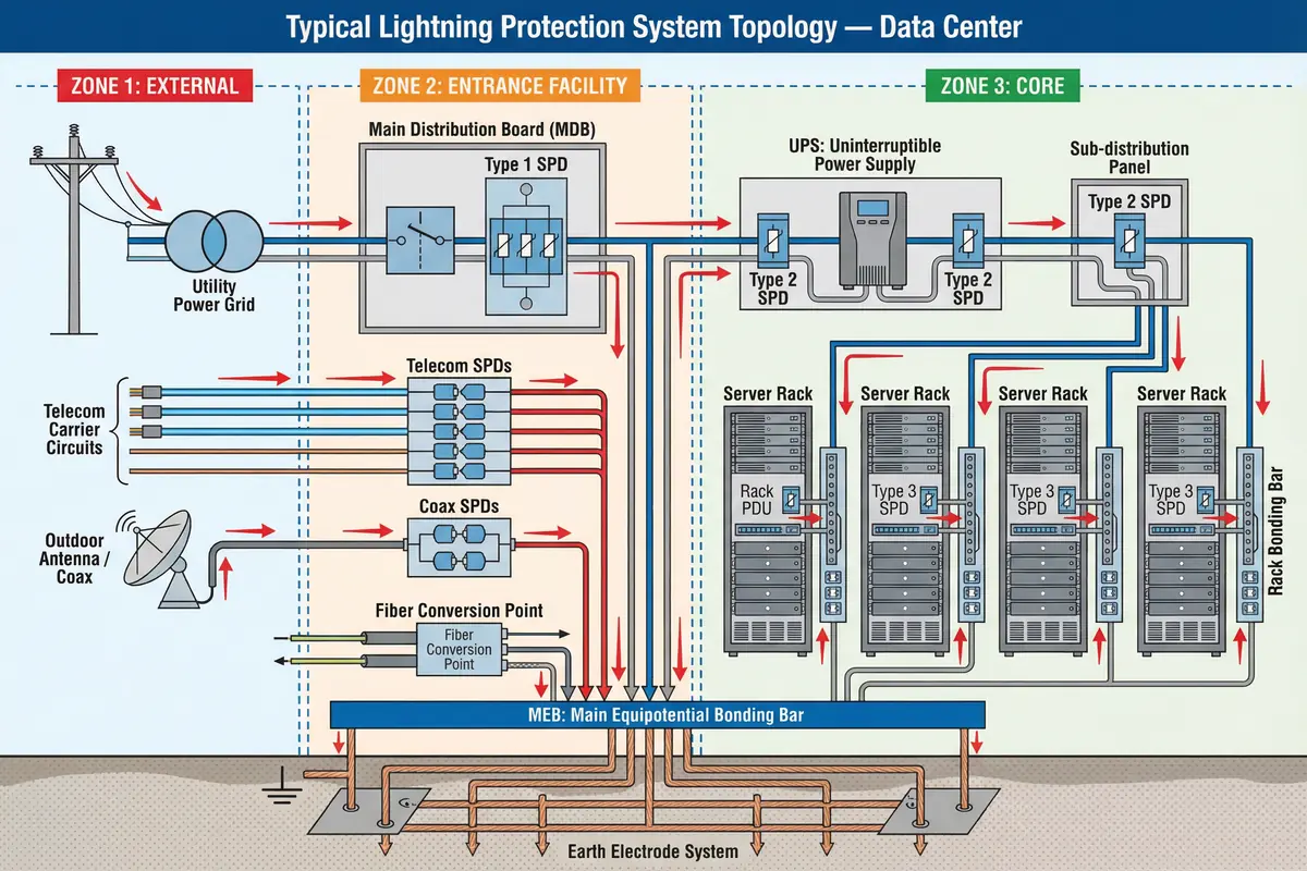
The typical lightning protection system for a data center or network room is organized around three protection zones, each with defined boundaries and protection measures. The topology diagram below illustrates the complete system from the external environment through the entrance facility to the core equipment zone, showing the surge current paths, SPD locations, and the central role of the Main Equipotential Bonding Bar (MEB).
Zone Definitions and Boundaries
The three-zone architecture provides a structured framework for applying protection measures at the appropriate locations. Zone boundaries are defined by physical barriers (walls, floors) and electrical boundaries (fiber conversion points, SPD locations). The key principle is that surge energy is progressively reduced at each zone boundary, so that by the time power or signal reaches the core equipment, the residual voltage is within the equipment's withstand capability.
| Zone | Location | Lightning Threat Level | Primary Protection Measures | Boundary Definition |
|---|---|---|---|---|
| Zone 1: External | Outside the building boundary | Highest — direct exposure to lightning environment | External LPS (air terminals, down conductors, earth electrodes) — outside scope of this guide | Building wall/roof boundary |
| Zone 2: Entrance Facility | Building entry point — MDB, MDF, demarc room | High — all external lines enter here; GPR risk | Type 1 power SPD, telecom/coax SPDs, fiber conversion, MEB, penetration register | Service entry point; fiber conversion; zone SPD locations |
| Zone 3: Core | Equipment rooms, server rooms, IDF closets | Reduced — residual surges after Zone 2 protection | Type 2/3 power SPDs, cabinet signal SPDs, rack bonding, cable routing control | Room boundary; SPD at distribution panel |
Surge Current Path Design
The topology is designed so that surge current flows along the intended path: from external lines through SPDs, via short bonding leads to the MEB, and then to the earth electrode system. This path must be lower impedance than any alternative path through equipment. The MEB is the central node of this path — every SPD earth lead, every rack bonding conductor, and every metallic service bond connects to the MEB. The earth electrode system provides the ultimate current sink.
Power Distribution Topology and SPD Placement
The power distribution topology determines where SPDs must be placed. The single-line diagram (SLD) must be reviewed to identify all power paths, including normal, UPS bypass, generator, and ATS paths. SPDs must be placed on every path that can carry surge energy to the equipment. A common oversight is omitting the UPS bypass path, which leaves equipment unprotected during bypass operation.
| Power Distribution Point | SPD Type | Typical Ratings | Notes |
|---|---|---|---|
| Main Distribution Board (MDB) / Service Entry | Type 1 (or Type 1+2 combined) | Iimp ≥ 12.5 kA/pole; Up ≤ 2.5 kV | Mandatory if overhead supply or high exposure; backup fuse required |
| UPS Input | Type 2 | In ≥ 20 kA/pole; Up ≤ 1.5 kV | Protects UPS from surges passing Type 1; include bypass path |
| UPS Output / Sub-distribution Panel | Type 2 | In ≥ 20 kA/pole; Up ≤ 1.2 kV | Protects downstream distribution and rack PDUs |
| Rack PDU / Equipment Power Strip | Type 3 | In ≥ 3 kA/pole; Up ≤ 0.8 kV | Final protection for sensitive equipment; low Up critical |
| Generator / ATS Output | Type 2 | In ≥ 20 kA/pole; Up ≤ 1.5 kV | Often overlooked; required if generator supply can reach equipment |
4.2 Equipment Wiring and Connection Diagram
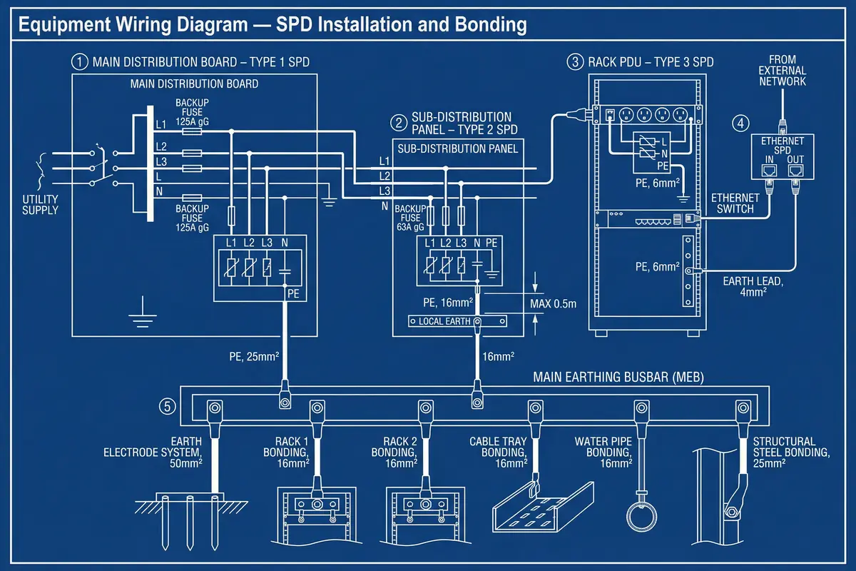
The equipment wiring diagram provides the detailed connection information needed for installation. It shows the conductor routing from the utility supply through each SPD stage to the equipment, the bonding conductor connections to the MEB, and the remote alarm wiring. The diagram below covers the five main wiring areas: Type 1 SPD at MDB, Type 2 SPD at sub-distribution, Type 3 SPD at rack PDU, Ethernet SPD at switch, and the MEB bonding network.
Critical Wiring Rules
The wiring diagram enforces several critical rules that must be followed during installation. These rules are derived from the physics of surge current behavior and cannot be relaxed without compromising protection effectiveness. The most important rules concern SPD lead length, conductor routing, and the connection of all earth leads to the same bonding reference.
| Rule | Requirement | Rationale | Verification Method |
|---|---|---|---|
| SPD PE lead length | As short as possible; target ≤ 0.5 m straight | Inductive voltage rise (V=L×di/dt) adds to clamping voltage; long leads negate SPD effectiveness | Measure installed lead length; verify straight routing without coils |
| No coiled leads | All SPD leads must be straight; no coils or loops | Coiled conductor has much higher inductance than straight conductor of same length | Visual inspection; reject any coiled or looped leads |
| Common bonding reference | All SPD PE leads connect to the same bonding bar/MEB | Different reference points create potential differences during surge; equipment damaged by differential voltage | Trace all PE leads to single MEB; verify no separate "clean earth" isolated from PE |
| Backup protection device | Fuse or MCB upstream of each SPD as specified by manufacturer | Prevents overheating and fire if SPD fails short under follow-current | Verify backup device type and rating matches SPD specification; check labeling |
| Conductor sizing | Bonding conductors sized per IEC 60364-5-54 and SPD manufacturer requirements | Undersized conductors have excessive impedance and may overheat under surge current | Verify conductor cross-section against design schedule; check connections are tight |
4.3 Earthing and Bonding Topology
The earthing and bonding topology defines the physical network of conductors that connects all metallic parts of the facility to a common equipotential reference. The topology must be designed to minimize impedance between any two points in the bonding network, particularly during the fast-rising surge currents of a lightning event. The MEB is the central node, and all bonding conductors radiate from it in a star topology to avoid creating loops that could carry circulating currents.
MEB Location and Sizing
The MEB must be located as close as possible to the main service entry and the main distribution board to minimize the length of SPD PE leads. In a multi-floor building, a local bonding bar (LBB) may be installed on each floor, connected back to the MEB by a main bonding conductor. The MEB must have sufficient terminals for all current connections plus at least 20% spare capacity for future additions. Each terminal must be labeled with a unique identifier matching the as-built drawings.
| Bonding Connection | Conductor Size (Typical) | Connection Method | Notes |
|---|---|---|---|
| Earth electrode to MEB | 50 mm² minimum (project-specific) | Bolted lug; anti-oxidation compound | Test link for earth resistance measurement |
| MDB PE to MEB | 25 mm² minimum | Bolted lug | Short, straight run; avoid routing near signal cables |
| Rack bonding bar to MEB | 16 mm² minimum | Bolted lug or bonding strap | One conductor per rack; labeled at both ends |
| Cable tray to MEB | 16 mm² minimum | Bonding clamp on tray; bolted to MEB | Bond at regular intervals; bond across all joints |
| Metallic services (water, gas, HVAC) | 16 mm² minimum | Bonding clamp; anti-oxidation compound | Bond at entry point; before any isolation valve |
| Structural steel | 25 mm² minimum | Bolted lug or welded connection | Bond at multiple points for large structures |
Cable Tray Bonding Strategy
Cable trays serve as the primary EMC return path for high-frequency currents and must be electrically continuous throughout the installation. Every joint between tray sections must be bridged with a flexible bonding jumper because the mechanical joint alone does not provide reliable electrical continuity. The tray system must be bonded to the MEB at regular intervals, with the bonding conductor connected at the tray joint nearest to the MEB. Paint must be removed from contact surfaces before installing bonding clamps, and anti-oxidation compound applied to prevent corrosion.