Chapter 5: Selection & Interfaces
5.1 Core Product Introduction
Lightning protection for network and data systems requires a coordinated set of products, each designed for a specific interface type and protection level. The core product range covers power SPDs from Type 1 through Type 3, signal SPDs for Ethernet/PoE, RS-485/serial, and coaxial interfaces, plus monitoring accessories. Selecting the correct product for each application requires matching the product's ratings to the site's exposure level, the interface's electrical characteristics, and the downstream equipment's withstand capability.
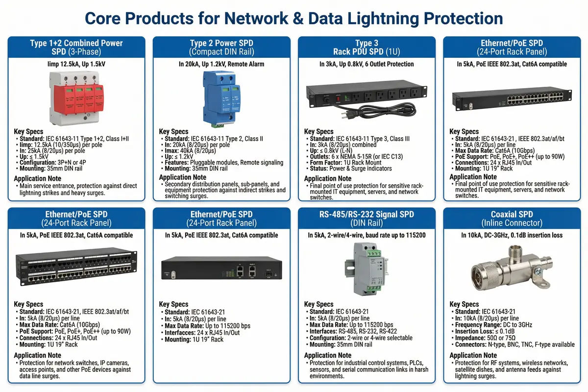
Product Family Overview
The product family is organized into three main groups: power protection, signal/data protection, and monitoring accessories. Within each group, products are differentiated by their protection level (impulse current rating), interface compatibility, and form factor. The selection process must consider all three dimensions simultaneously to ensure that the selected product provides adequate protection without degrading the protected signal or power quality.
| Product Group | Product Type | Key Rating | Form Factor | Primary Application |
|---|---|---|---|---|
| Power Protection | Type 1+2 Combined SPD | Iimp ≥ 12.5 kA/pole | DIN rail, 3P+N or 4P | MDB/service entry with overhead supply |
| Type 2 Power SPD | In ≥ 20 kA/pole | DIN rail, 1P/2P/3P+N | Sub-distribution panels, UPS input/output | |
| Type 3 Rack PDU SPD | In ≥ 3 kA/pole | 1U rack mount | Rack PDU, equipment power strip | |
| Signal/Data Protection | Ethernet/PoE SPD | In ≥ 5 kA/line | 1U rack panel, 24-port | Switch ports for outdoor/external Ethernet |
| RS-485/RS-232 SPD | In ≥ 5 kA/line | DIN rail, 2-wire/4-wire | PLC/SCADA field device connections | |
| Coaxial SPD | In ≥ 10 kA | Inline connector | Antenna feeders, CCTV coax, RF systems | |
| Monitoring Accessories | SPD Remote Alarm Module | NC/NO contact | Integrated or add-on | NMS/BMS integration for SPD health monitoring |
| Earth Resistance Test Link | N/A | Disconnectable link | MEB and bonding bars for periodic testing |
5.2 Typical Wiring and Interface Logic
The interface logic diagrams define the correct wiring for each SPD type, including the signal path (IN to OUT), the earth connection (to bonding bar), and any auxiliary connections (alarm contacts, DC pass/block). Correct wiring is essential for both protection effectiveness and signal integrity. Incorrect wiring — such as reversed IN/OUT connections or missing earth leads — can result in no protection, signal degradation, or equipment damage.
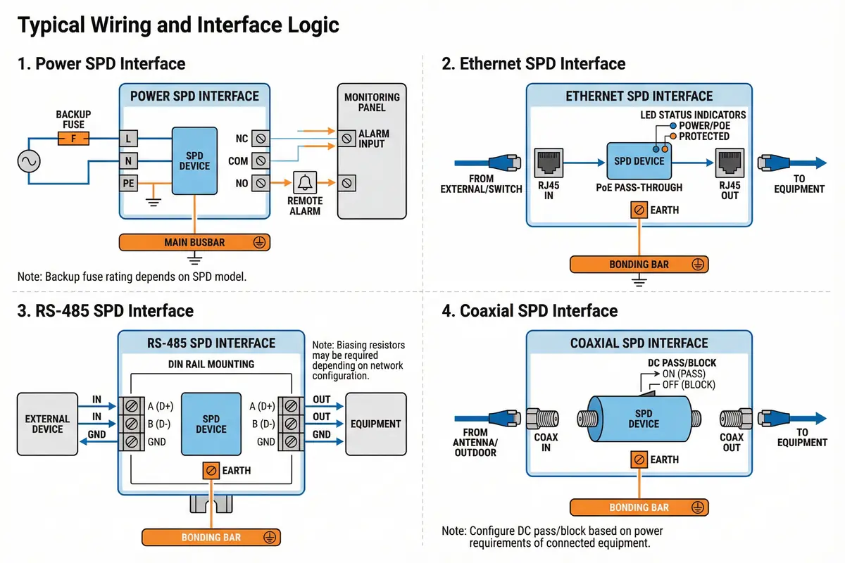
Interface-Specific Wiring Notes
Each interface type has specific wiring requirements that go beyond the basic IN-OUT-Earth connection. The following notes highlight the most critical interface-specific considerations that must be addressed during design and verified during installation.
| Interface Type | Critical Wiring Consideration | Common Error | Verification Step |
|---|---|---|---|
| Power SPD | Backup fuse/MCB upstream; PE lead ≤ 0.5 m straight to bonding bar; remote alarm contacts wired to monitoring system | No backup device; long coiled PE lead; alarm contacts not connected | Measure PE lead length; verify backup device rating; test alarm contact operation |
| Ethernet/PoE SPD | IN port from external/switch; OUT port to protected equipment; earth lead to bonding bar; PoE budget verified after SPD insertion | IN/OUT reversed; earth lead missing; PoE budget not checked | Verify port orientation; measure PoE voltage at equipment; check LED status indicators |
| RS-485 SPD | A(D+)/B(D-)/GND terminals correctly matched; biasing resistors may need adjustment; earth lead to bonding bar; baud rate compatibility verified | A/B reversed causing communication failure; biasing not adjusted; earth lead missing | Verify A/B polarity; test communication at maximum baud rate; verify earth connection |
| Coaxial SPD | IN from antenna/outdoor; OUT to equipment; DC pass or DC block selected based on whether DC power is supplied via coax; earth lead to bonding bar | DC pass/block misconfigured; earth lead missing; wrong connector type | Verify DC pass/block setting; measure insertion loss at operating frequency; verify earth connection |
5.3 Core Product Function Table
The product function table provides a comprehensive reference for all core products, covering their protection function, key electrical parameters, compatibility requirements, and selection criteria. This table is intended to support the product selection process by presenting all relevant information in a single reference.
| Product | Protection Function | Key Electrical Parameters | Compatibility Requirements | Selection Criteria |
|---|---|---|---|---|
| Type 1+2 Combined Power SPD | Intercepts direct lightning current and switching surges at service entry; limits overvoltage to Up | Iimp ≥ 12.5 kA/pole; In ≥ 20 kA/pole; Up ≤ 1.5 kV; Uc ≥ 1.1 × Un | Backup fuse/MCB per manufacturer spec; TN-S or TN-C-S earthing; 3P+N or 4P configuration | Required if overhead supply or LPL I/II; Iimp based on LPL; Up must be below equipment withstand |
| Type 2 Power SPD | Limits residual surge energy after Type 1; protects distribution equipment and UPS | In ≥ 20 kA/pole; Imax ≥ 40 kA/pole; Up ≤ 1.2 kV; Uc ≥ 1.1 × Un | Backup fuse/MCB per manufacturer spec; pluggable modules preferred for easy replacement | Required at all distribution panels; Up must coordinate with Type 1 and Type 3; remote alarm preferred |
| Type 3 Rack PDU SPD | Final protection for sensitive rack-mounted equipment; lowest Up in the cascade | In ≥ 3 kA/pole; Up ≤ 0.8 kV; Uc ≥ 1.1 × Un; outlet type per region | Compatible with rack PDU outlet type; load current rating ≥ total rack load; no additional backup device if internally protected | Required at all rack PDUs; Up ≤ 0.8 kV for sensitive electronics; select outlet type for region |
| Ethernet/PoE SPD (24-port) | Protects switch ports from differential and common-mode surges on Ethernet/PoE lines | In ≥ 5 kA/line; Up ≤ 50 V; bandwidth ≥ 10 Gbps (Cat6A); PoE IEEE 802.3af/at/bt | Ethernet category compatibility (Cat5e/6/6A); PoE standard compatibility; insertion loss within Ethernet budget | Required for all outdoor or external copper Ethernet; verify PoE budget; select port count to match switch |
| RS-485/RS-232 Signal SPD | Protects serial communication lines from induced surges on long field cable runs | In ≥ 5 kA/line; Up ≤ 50 V; insertion resistance ≤ 1 Ω; baud rate up to 115200 bps | A/B/GND terminal compatibility; biasing resistor compatibility; baud rate compatibility; DIN rail mounting | Required for all RS-485 field cables; verify biasing with PLC vendor; select 2-wire or 4-wire per system |
| Coaxial SPD | Protects RF equipment and antenna feeders from lightning surges on coaxial cables | In ≥ 10 kA; Up ≤ 50 V; frequency range DC-3 GHz; insertion loss ≤ 0.1 dB; impedance 50 Ω or 75 Ω | Connector type (N, BNC, TNC, F); impedance matching; DC pass or DC block per system requirement | Required for all outdoor coax; verify frequency range covers operating band; select DC pass/block per system |
SPD Coordination Verification
After selecting individual products, the coordination between stages must be verified. The residual voltage (Up) of each upstream SPD must be higher than the Up of the downstream SPD, ensuring that the upstream stage handles the bulk of the energy. The energy coordination between stages is typically verified by the SPD manufacturer through testing, but the designer must confirm that the selected combination has been tested or that the energy coordination margin is sufficient based on the installation distances and cable inductance between stages.
Coordination Rule: Up(Type 1) > Up(Type 2) > Up(Type 3). The downstream SPD must have a lower clamping voltage than the upstream SPD. If the voltage protection levels are too close, the downstream SPD may absorb too much energy and fail prematurely. Consult the SPD manufacturer for coordination verification if stages are installed less than 10 m apart.