Chapter 7: Support & Integration
This chapter covers the mandatory integration requirements for lightning protection with the following companion systems: communications and networking, UPS, power distribution, lightning and earthing infrastructure, room infrastructure, fire linkage, and physical security. Each companion system has specific interface requirements that must be addressed in the design to ensure that the complete installation provides the intended level of protection.
7.1 Companion Equipment — Complete Integration Overview
The following diagram presents all companion equipment and accessories required for a complete lightning protection installation in a single integrated view. Each equipment category is shown with its key specifications, part number format, and application context. This integrated overview ensures that no companion equipment is overlooked during the design and procurement process.
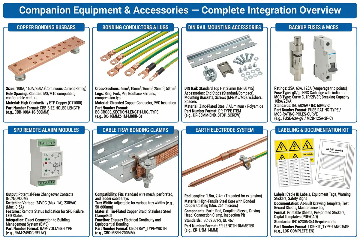
Support System Categories and Requirements
Each companion system category has specific necessity, capacity, failure risk, and acceptance requirements. The table below summarizes these requirements for all seven companion system categories covered in this chapter.
| Companion System | Necessity | Key Capacity Requirements | Primary Failure Risks | Acceptance Focus |
|---|---|---|---|---|
| A. Communications & Networking | Network topology defines where copper exists and therefore where surges can enter | Fiber uplinks for inter-zone; redundant links for core; managed switches with port-level monitoring | Uncontrolled copper entry; bypass patching across zone boundaries; poor shielding | Penetration register audit; patch mapping; fiber boundary verification; port labeling |
| B. UPS | UPS changes fault paths; bypass path can bypass protection if not covered | N+1 for critical sites; surge protection on all paths including bypass and generator | Missing SPD on bypass path; bonding omitted from UPS frame; incorrect SPD on UPS output | Verify all UPS paths in SPD schedule; bond continuity test on UPS frame; simulate bypass event |
| C. Power Distribution (MDB/RPP/PDU) | Primary surge entry path; all external power enters through distribution | Feed sizing per load; spare ways for future SPDs; backup protection devices for each SPD | Wrong backup protection rating; long SPD leads; SPD on wrong phase configuration | Panel inspection checklist; verify backup device ratings; thermal scan after commissioning |
| D. Lightning Protection & Earthing | Defines reference and surge dissipation path; must be robust and accessible | Robust electrode system; accessible test points; documented bonding network | Corrosion of outdoor connections; loosened lugs; undocumented modifications to earthing system | Earth resistance measurement; continuity mapping; test point accessibility verification |
| E. Room Infrastructure (Flooring, Trays, HVAC, Pipes) | Metal structures can float and create differential potentials during GPR events | Bonding at all tray joints; HVAC frame bonding; metallic pipe bonding at entry point | Tray joint discontinuity; unbonded pipes; raised floor pedestals not bonded | Visual inspection; continuity testing of tray sections; verification of pipe bonding at entry |
| F. Fire Linkage | Fire systems share conduits and metallic pathways; must not become surge conduits | Separate conduits for fire system cables; bonded metallic conduits; SPD alarm wiring routed separately | Shared conduits with external lines; miswiring of fire system I/O; surge on fire panel | Interface test; routing audit; verify separation from surge-prone entries |
| G. Physical Security & Protective Products | Security devices often extend outdoors; outdoor camera and access control lines are surge paths | Fiber preferred for outdoor camera links; PoE SPDs for copper camera connections; bonded access control frames | Outdoor camera copper lines bring surges to NVR/access control panel; unbonded door frames | Fiber use verified for outdoor links; any copper protected with SPDs and bonded; door frame bonding check |
7.2 Cross-System Interfaces and Integration
The cross-system interface table defines the specific integration points between companion systems, the controls that must be applied at each interface, and the test method for verifying correct integration. Each interface point represents a potential failure mode if not correctly designed and installed.
| System A | System B | Interface Type | What Must Be Controlled | Typical Failure Mode | Integration Test |
|---|---|---|---|---|---|
| Power distribution | UPS | Power + PE bonding | SPD coverage on input, output, and bypass paths; UPS frame bonded to MEB | Surge enters on bypass path; UPS frame floating | Simulate bypass event; verify SPDs on all paths; continuity test on UPS frame bond |
| Networking | Physical security | Signal (Ethernet/coax) | Outdoor links fiber-first; PoE SPDs on copper outdoor links; bonded camera frames | PoE port damage from outdoor camera surge; NVR damage | Verify link type (fiber/copper); verify SPD on copper outdoor links; alarm test |
| Earthing | Building LPS | Bonding connection | Controlled bonding point between site earth and building LPS; short, low-inductance path | Dangerous potential difference between LPS down conductors and site earth during strike | Visual inspection of bonding connection; continuity test; verify no isolated metallic structures |
| Room infrastructure | Networking | Physical routing | Separation between power and data cable trays; tray bonding at joints; no parallel runs near down conductors | EMI coupling from power to data cables; arcing at unbonded tray joints | Route inspection; measure separation distances; continuity mapping of tray sections |
| SPD alarms | Monitoring/NMS | Control/I/O | Secure wiring of alarm contacts; correct mapping in NMS; alarm tested and documented | Silent exposure — SPD fails but no alarm generated; incorrect alarm mapping | Simulate SPD alarm contact (open/close); verify NMS receives and classifies alarm; check mapping document |
| Fire linkage | Power distribution | Control/I/O + power | Fire panel I/O isolated from surge-prone entries; fire system cables in separate bonded conduits | Surge on fire panel I/O causes false alarm or panel damage | Routing audit; verify separation; functional test of fire panel I/O after installation |
7.3 Physical Interface Inventory and Common Installation Errors
The physical interface inventory lists each interface point in the installation, its correct implementation, and the most common installation errors observed in practice. Each error is accompanied by its consequence and the corrective action. This inventory serves as a checklist for installation inspection and acceptance testing.
| Interface Point | Physical Location | Correct Practice | Common Error | Consequence | Corrective Action |
|---|---|---|---|---|---|
| External power entry SPD | Main distribution board (MDB) | Type 1/2 SPD with short PE lead ≤ 0.5 m straight to MEB; correct backup device upstream | SPD installed far from entry; long coiled PE lead; wrong backup device | High residual voltage reaches downstream equipment; fire risk if SPD fails | Relocate SPD closer to entry; shorten and straighten PE lead; replace backup device |
| Demarc copper entry | Entrance facility / MDF room | Signal SPD or fiber conversion at demarc; all entries registered in penetration register; bonded metallic conduits | Uncontrolled wall penetration; no SPD; no penetration register entry | Unknown surge path directly to core equipment; no protection | Install SPD or convert to fiber; register penetration; seal and bond conduit |
| Coaxial cable entry | Entry plate or MDF | Coaxial SPD at entry plate; shield bonded to entry plate with wide strap; entry plate bonded to MEB | Shield not bonded at entry; coax SPD missing; entry plate isolated from MEB | Arcing at entry point; EMI injection; RF equipment damage | Install coax SPD; bond shield at entry plate; bond entry plate to MEB |
| Rack bonding bar | Rack side rail or 1U panel | Bonding bar with dedicated jumpers to major chassis; bonding bar connected to MEB via bonding conductor | Painted contact surfaces; missing bonding bar; bonding conductor too long | Intermittent bonding; rack-to-rack potential difference during GPR | Remove paint from contact surfaces; install bonding bar; shorten bonding conductor |
| Cable tray joints | Overhead or underfloor trays | Flexible bonding jumper across every tray joint; tray bonded to MEB at regular intervals | No bonding straps at joints; paint on contact surfaces; tray not bonded to MEB | Spark gaps at joints; EMI injection; arcing under surge current | Add bonding jumpers at all joints; remove paint; add tray-to-MEB bonding conductors |
| UPS bypass path | UPS bypass distribution panel | SPD on bypass path consistent with cascade coordination; bypass path included in SPD schedule | SPD only on normal output path; bypass path unprotected | Equipment unprotected during bypass operation; surge damage during maintenance | Add SPD to bypass distribution; update SPD schedule; verify coordination |
7.4 Support System Fault Impact Chain
Understanding the fault impact chain for each companion system helps prioritize maintenance activities and design redundancy. The following descriptions trace the fault chain from initial failure through to the ultimate impact on network availability and equipment integrity.
| Support System | Maintenance Focus | Fault Chain | Monitoring Method |
|---|---|---|---|
| UPS | Battery tests; event log review; bypass path SPD verification | SPD failure → surge reaches UPS controls → UPS transfer to bypass → downstream equipment resets or fails | UPS event log; SPD remote alarm; NMS link status monitoring |
| Cabling (Fiber/Copper) | Fiber connector cleaning; optical power monitoring; copper link error rate monitoring | Copper bypass patch installed → surge hits switch port → link flap → routing instability → service disruption | NMS port error counters; optical power levels; patch panel audit |
| Earthing & Bonding | Corrosion checks; periodic earth resistance measurement; torque verification | Bond loosens → local potential rise during GPR → repeated small equipment damages → latent failures accumulate | Periodic low-ohm continuity tests; earth resistance measurement; visual inspection |
| Power Distribution | SPD status inspection; backup device verification; thermal scan | SPD degrades silently → next surge not clamped → equipment damage → service outage | SPD remote alarm contacts; visual status indicators; thermal camera inspection |