Chapter 8: Tools & Accessories
This chapter lists the accessories, tools, and consumables that directly affect lightning protection installation quality. Installation quality is often the deciding factor between "SPDs installed" and "system protected." The correct accessories ensure low-impedance bonding connections, proper SPD mounting, and reliable long-term performance. The typical parts list provides a bill of materials reference for a standard network room installation.
8.1 Accessory List
The following table presents the complete accessory list for a lightning protection installation, covering bonding hardware, mounting accessories, protection devices, and documentation materials. Each accessory is described with its specification, use, selection tips, low-quality risk, and inspection method.
| Product Name | Description | Specification | Use | Selection Tips | Low-Quality Risk | Inspection Method |
|---|---|---|---|---|---|---|
| MEB Busbar | Main equipotential bonding bar; copper or tinned copper; multiple bolt terminals | ETP copper or tinned; M8/M10 terminals; rated current per design; mounting insulators | Central bonding reference for all SPD PE leads, rack bonds, and service bonds | Enough terminals for all connections plus 20% spare; verify current rating | Overheating at undersized terminals; poor contact resistance; corrosion at untinned terminals | Visual check; torque check; low-ohm continuity test between terminals |
| Rack Bonding Bar | Small copper bonding bar for rack-level equipotential; 1U or side rail mount | ETP copper; 6–10 terminals; M6/M8 studs; 1U rack or side rail mount | Local bonding reference for rack equipment; connects to MEB via bonding conductor | Match form factor to rack; verify terminal count for equipment plus SPD leads | Insufficient terminals; poor contact with rack frame; high impedance to MEB | Visual; continuity test rack frame to MEB via bonding bar |
| Bonding Strap / Wide Braid | Flat braided copper strap for low-inductance bonding connections | Tinned copper braid; 16–50 mm² equiv.; flexible; corrosion-resistant end fittings | Low-inductance bonding where straight conductor is impractical; tray joints; door bonds | Select wide and short; avoid narrow round conductors for HF bonding | High inductance if narrow/long; corrosion at end fittings; reduced HF effectiveness | Measure length/width; check end fittings; continuity test |
| Cable Tray Bonding Kit | Flexible copper jumpers with clamps for bonding across tray joints | Flexible copper; 16 mm² min.; clamps for mesh/perforated/ladder tray types | Electrical continuity across every tray joint; prevents arcing under surge current | Clamp type compatible with tray material; one jumper per joint minimum | Arcing at unbonded joints; EMI injection; tray sections at different potentials | Continuity mapping by tray section; visual clamp inspection |
| Shield Clamp (360°) | EMC-rated cable shield termination clamp for 360° shield bonding | Stainless or tinned steel; compatible with cable OD range; EMC-rated | Correct shield termination to bonding bar; prevents EMI from pigtail connections | Match clamp OD to cable; avoid pigtail terminations for HF shielding | EMI leakage from incomplete shield contact; pigtail high inductance at HF | Visual; verify 360° contact; check cable OD vs. clamp range |
| Earth Test Link | Disconnectable link for earth resistance measurement at MEB | Lockable disconnecting link; rated current per design; accessible; labeled | Allows earth resistance measurement without disconnecting all bonding conductors | Select accessible location; label and document in as-built drawings | Cannot measure earth resistance without full disconnection; undocumented test point | Functional test — disconnect and reconnect; verify label vs. as-built drawing |
| Labeling Kit | Cable labels, equipment tags, warning stickers, and as-built documentation templates | Heat-shrink or self-laminating labels; standardized naming; warning stickers per code | Identifies all bonding conductors, SPDs, test points, and protected/unprotected ports | Standardized naming; label both ends of every conductor; include installation date | Mismaintenance from unlabeled connections; inability to trace conductors | Audit labels vs. as-built drawings; verify both ends of conductors labeled |
8.2 Installation Tools
The following tools are essential for achieving correct installation quality. Using the correct tools — particularly calibrated torque wrenches and low-ohm meters — is the difference between a compliant installation and one that appears compliant but will fail under surge conditions.
| Tool Name | Description | Use | Key Parameters | Misuse Risk | Installation Stage |
|---|---|---|---|---|---|
| Torque Wrench | Calibrated wrench for controlled tightening of bonding connections and SPD terminals | Tightening lugs, busbar terminals, bonding clamps, and SPD mounting hardware to specified torque | Range 2–50 N·m; calibrated; appropriate drive size for terminal types | Loose connections (under-torque) or damaged threads (over-torque); increased contact resistance | Installation and commissioning; re-verification at periodic inspection |
| Low-Ohm Meter (4-wire) | Precision resistance meter using 4-wire (Kelvin) measurement for accurate low-resistance readings | Bonding continuity verification from racks, trays, and SPD PE leads to MEB; acceptance testing | 4-wire preferred; range 0.001–10 Ω; calibrated; test current per standard | 2-wire measurement gives false pass due to test lead resistance; incorrect baseline | Acceptance testing; periodic O&M; post-event inspection |
| Hydraulic Crimp Tool | Hydraulic or ratchet crimp tool for terminating bonding conductors with compression lugs | Crimping copper lugs onto bonding conductors; ensures gas-tight, low-resistance connection | Die set matching lug and conductor cross-section; correct die for copper | Wrong die size creates cold joint with high resistance; joint may overheat under surge | Installation; conductor preparation |
| Thermal Camera (IR) | Infrared thermal imaging camera for detecting hot spots in electrical panels and bonding connections | Identifying overheating at loose connections, undersized conductors, and degraded SPDs under load | Sensitivity ≤ 0.1°C; resolution for panel inspection; emissivity adjustment | Missing hot spots if insufficient load during inspection; incorrect emissivity setting | Commissioning under load; periodic inspection; post-event inspection |
| Earth Resistance Tester | Dedicated instrument for measuring earth electrode resistance and soil resistivity | Measuring earth electrode resistance at MEB test link; verifying against design target | Fall-of-potential or stakeless method; frequency-based; calibrated | Incorrect test method; interference from nearby power cables; misinterpretation of results | Acceptance testing; annual O&M inspection |
8.3 Consumables
Consumables are often overlooked in lightning protection installations, but they have a significant impact on long-term connection quality and system reliability. The use of correct consumables — particularly anti-oxidation compound and corrosion-resistant fasteners — is essential for outdoor and high-humidity installations where connection degradation is a primary failure mode.
| Consumable | Description | Specification | Use | Why It Affects Stability | Low-Quality Risk | Recommended Practice |
|---|---|---|---|---|---|---|
| Anti-Oxidation Compound | Electrical-grade compound applied to metal contact surfaces to prevent oxidation | Electrical-grade; compatible with copper and aluminum; not general-purpose grease | Applied to lug/busbar surfaces before tightening; prevents oxidation layer forming | Oxidation increases contact resistance; resistance rise causes heating and failure | Increased contact resistance over time; hot joints; intermittent bonding | Apply thin layer to cleaned surface before tightening; re-apply at periodic inspection |
| Heat-Shrink Sleeves (Adhesive-Lined) | Dual-wall heat-shrink tubing with adhesive inner layer for waterproof insulation | Adhesive-lined; correct shrink ratio for conductor size; rated temperature range | Insulating and sealing conductor terminations; preventing moisture ingress at lug connections | Moisture ingress causes corrosion and resistance rise; critical outdoors | Water ingress; corrosion at termination; conductor damage | Use correct size; apply heat evenly; verify adhesive has flowed at both ends |
| Stainless Steel Fasteners | Grade 304 or 316 stainless steel bolts, nuts, and washers for outdoor bonding | Grade 304 (indoor/mild outdoor) or 316 (coastal/aggressive); lock washers included | Fastening bonding connections in outdoor or high-humidity environments; prevents rust | Rust causes loosening and increased contact resistance; critical for outdoor bonds | Rust and corrosion; loose connections; increased impedance | Use lock washers; apply torque mark after tightening; inspect at periodic maintenance |
| IP-Rated Cable Glands | Sealed cable entry glands for cabinet penetrations in outdoor or wet environments | IP55 minimum for outdoor; correct size for cable OD; metallic for bonding continuity | Sealing cable entries in outdoor cabinets; maintaining IP rating; bonding shield at entry | Unsealed penetrations allow moisture ingress; causes corrosion of internal connections | Water and corrosion inside cabinet; degraded connections; equipment failure | Select correct size; tighten to spec; verify seal after installation |
| Conduit Bonding Bushings | Metallic bushings for bonding metallic conduit to cabinet or panel at entry point | Rated for conduit size; compatible with conduit material; provides bonding lug | Bonding metallic conduit to cabinet frame at entry point; prevents floating conduit | Floating conduit can develop potential difference and act as unintended coupling path | Unintended coupling; arcing at conduit entry; EMI injection | Bond at entry point; verify continuity from conduit to cabinet frame to MEB |
8.4 Typical Installation Parts List
The following parts list provides a bill of materials reference for a typical network room lightning protection installation. Quantities are indicative for a medium-sized installation (4 server racks, 2 Ethernet SPD panels, 3 RS-485 field device connections, 2 coaxial antenna entries). Actual quantities must be determined from the site-specific design drawings and SPD schedule.
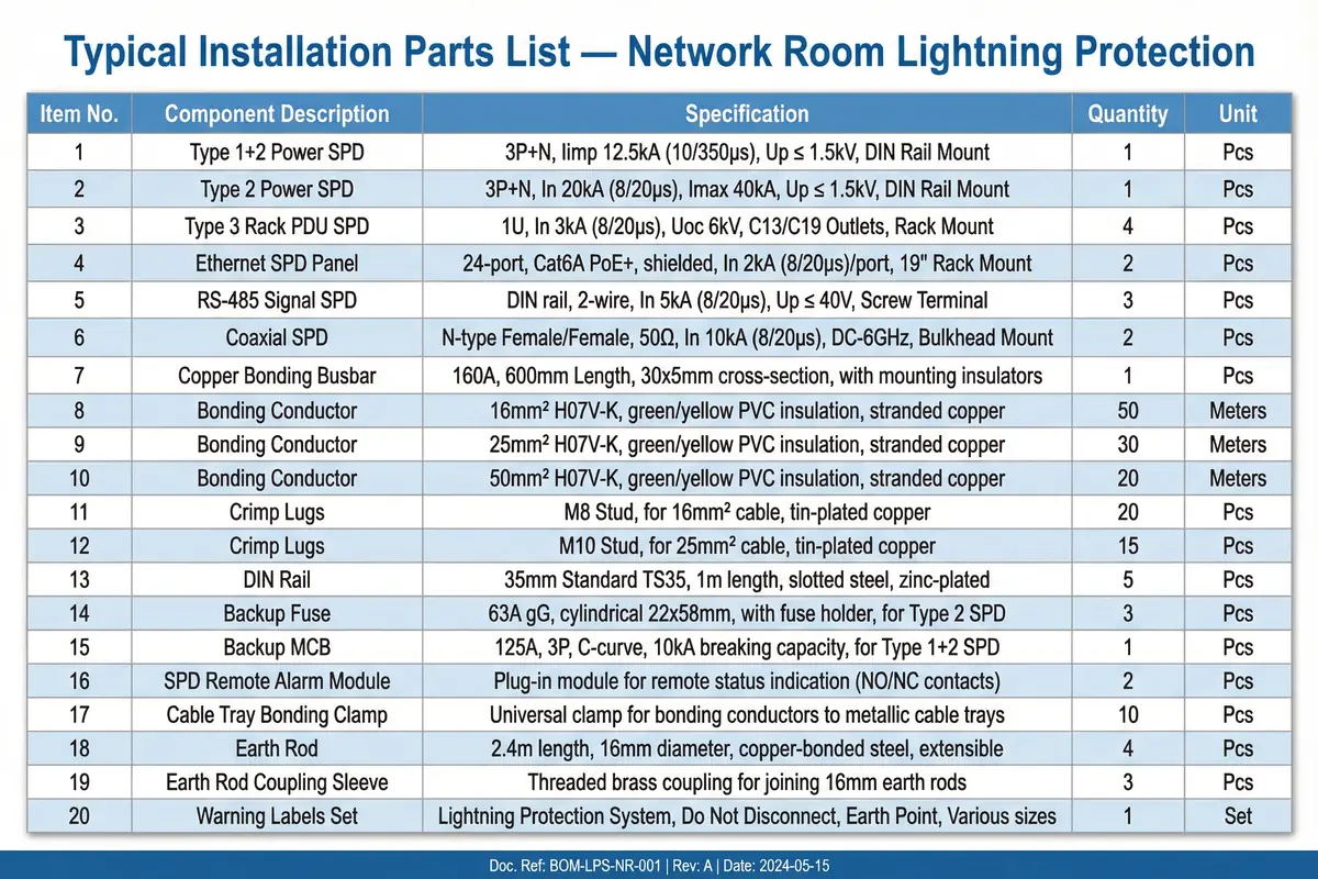
| Item | Component Description | Specification | Qty | Unit | Notes |
|---|---|---|---|---|---|
| 1 | Type 1+2 Combined Power SPD | 3P+N, Iimp 12.5 kA/pole (10/350 µs), Up ≤ 1.5 kV, DIN rail | 1 | Pcs | At MDB; backup MCB 125A required |
| 2 | Type 2 Power SPD | 3P+N, In 20 kA/pole (8/20 µs), Imax 40 kA, Up ≤ 1.2 kV, DIN rail | 2 | Pcs | At sub-distribution panels; backup fuse 63A gG |
| 3 | Type 3 Rack PDU SPD | 1U, In 3 kA (8/20 µs), Up ≤ 0.8 kV, 6 outlets C13/C19 | 4 | Pcs | One per rack PDU |
| 4 | Ethernet/PoE SPD Panel | 24-port, Cat6A, PoE IEEE 802.3at, In 5 kA/port, 1U rack mount | 2 | Pcs | For switch ports serving outdoor/external devices |
| 5 | RS-485 Signal SPD | DIN rail, 2-wire, In 5 kA (8/20 µs), Up ≤ 40 V, screw terminals | 3 | Pcs | For field device RS-485 connections |
| 6 | Coaxial SPD | N-type female/female, 50 Ω, In 10 kA (8/20 µs), DC-6 GHz | 2 | Pcs | For antenna/coax entries |
| 7 | MEB Copper Bonding Busbar | 160A, 600 mm length, 30×5 mm cross-section, with mounting insulators | 1 | Pcs | Main equipotential bonding bar |
| 8 | Rack Bonding Bar | 1U, 6 terminals M6, ETP copper, rack mount | 4 | Pcs | One per server rack |
| 9 | Bonding Conductor 16 mm² | H07V-K, 16 mm², green/yellow PVC, stranded copper | 50 | Meters | Rack-to-MEB bonding conductors |
| 10 | Bonding Conductor 25 mm² | H07V-K, 25 mm², green/yellow PVC, stranded copper | 30 | Meters | MDB PE to MEB; structural steel bonds |
| 11 | Bonding Conductor 50 mm² | H07V-K, 50 mm², green/yellow PVC, stranded copper | 20 | Meters | Earth electrode to MEB |
| 12 | Crimp Lugs M8 for 16 mm² | M8 stud, for 16 mm² cable, tin-plated copper | 20 | Pcs | Rack bonding conductor terminations |
| 13 | Crimp Lugs M10 for 25 mm² | M10 stud, for 25 mm² cable, tin-plated copper | 15 | Pcs | MDB and structural steel terminations |
| 14 | DIN Rail 35 mm | TS35, 1 m length, slotted steel, zinc-plated | 5 | Pcs | For mounting DIN rail SPDs and accessories |
| 15 | Backup Fuse 63A gG | 63A gG, cylindrical 22×58 mm, with fuse holder | 3 | Pcs | Upstream protection for Type 2 SPDs |
| 16 | Backup MCB 125A 3P | 125A, 3P, C-curve, 10 kA breaking capacity | 1 | Pcs | Upstream protection for Type 1+2 SPD |
| 17 | SPD Remote Alarm Module | Plug-in module, NO/NC contacts, 24 VDC/230 VAC compatible | 3 | Pcs | For critical SPDs requiring NMS integration |
| 18 | Cable Tray Bonding Clamp | Universal clamp for 50–200 mm tray width, tinned copper braid | 10 | Pcs | One per tray joint; additional at tray-to-MEB connections |
| 19 | Earth Rod 2.4 m | 2.4 m length, 16 mm diameter, copper-bonded steel, extensible | 4 | Pcs | Earth electrode system; quantity per soil resistivity |
| 20 | Warning Labels Set | "Lightning Protection System," "Do Not Disconnect," "Earth Point" — various sizes | 1 | Set | Applied to all SPDs, test points, and bonding bars |
Note: This parts list is indicative for a medium-sized installation. Actual quantities must be determined from site-specific design drawings and the SPD schedule. Always verify that selected products are compatible with the local electrical code, earthing system type (TN-S, TN-C-S, TT), and supply voltage. Consult the SPD manufacturer for coordination verification if multiple SPD stages are installed within 10 m of each other.