Lightning Protection and Grounding Design Guide for Network and Data Systems
A comprehensive engineering reference for designing lightning protection and earthing systems in data rooms, MDF/IDF, edge sites, telecom shelters, and outdoor network cabinets. Covers equipotential bonding, coordinated SPDs, shielding, cable routing, and O&M procedures.
System Overview
This guide defines an implementable engineering method to design lightning protection and earthing for network and data systems. The approach anchors everything to a site earthing network — comprising an earth electrode system and bonding network — then applies equipotential bonding, coordinated surge protective devices (SPDs), shielding and routing control, and line-entry governance so that lightning-related potential rise and overvoltage stay within equipment withstand limits.
The primary goal is to reduce service interruption, equipment damage, and latent failures caused by direct strikes nearby, induced surges, and ground potential rise (GPR). The design must be measurable, maintainable, and verifiable during acceptance and O&M. This guide is applicable to data rooms, MDF/IDF, edge compute nodes, telecom POPs, industrial network rooms with PLC/SCADA links, and campus demarc rooms supporting copper Ethernet, RS-485/RS-232/control, coax/feeder, and mixed fiber/copper environments.
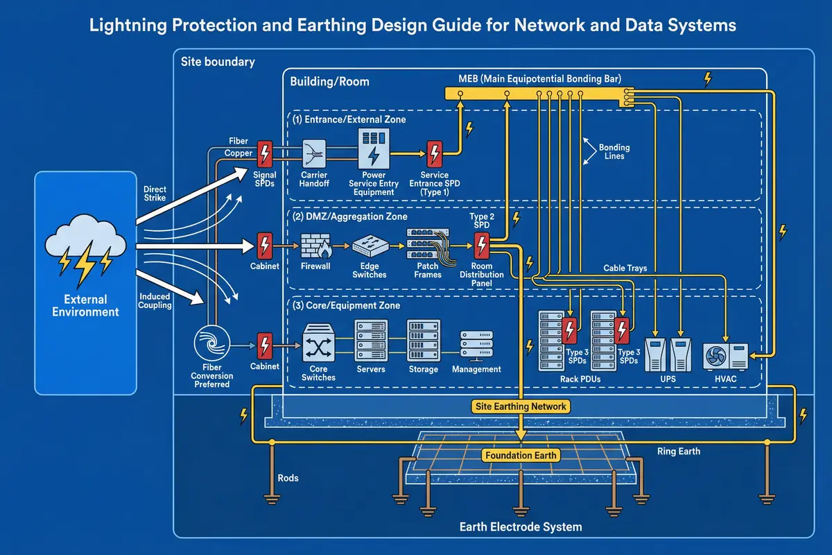
Core Value: This guide converts lightning protection into a system discipline — predictable surge paths, controlled bonding, and coordinated protective levels — rather than scattered "add an SPD" actions. The result is a bonded room where racks, trays, panels, and shields reference the same equipotential plane, with SPDs installed at the right locations and outside lines entering through governed points.
Main Functions
The system is organized around eight core functions, each contributing to the central objective of keeping all equipment within its withstand limits during lightning events. These functions span from the physical earthing infrastructure through surge protection, routing control, and operational monitoring.
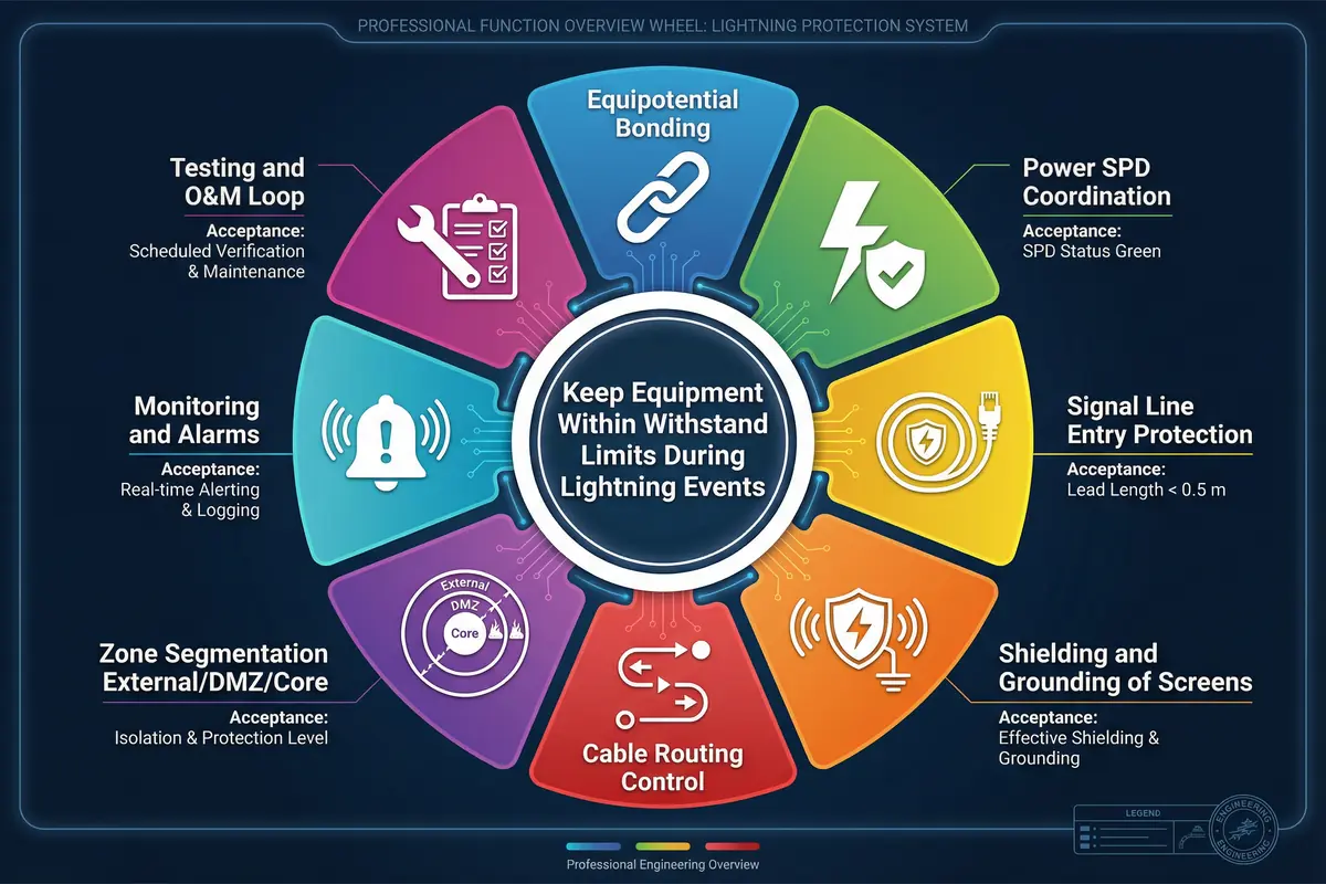
| # | Function | Value | Key Acceptance Criterion |
|---|---|---|---|
| 1 | Equipotential Bonding Backbone | Minimizes differential voltage between racks during GPR | Continuity measurements within specified limits |
| 2 | Coordinated Power SPD (Type 1/2/3) | Limits overvoltage step-by-step to protect downstream devices | SPD status green; lead length < 0.5 m |
| 3 | Signal Line Entry Governance | Prevents surges entering via network/control/coax lines | SPDs at entry; no uncontrolled penetrations |
| 4 | Shielding & Screen Bonding | Reduces induced noise while avoiding ground-loop currents | No pigtails in HF shielding; 360° clamps used |
| 5 | Cable Routing & Separation Control | Reduces inductive coupling between power and data | Separation distances maintained; crossings at right angles |
| 6 | Zone Segmentation (External/DMZ/Core) | Limits surge propagation between zones | Fiber boundaries documented; no copper bypass |
| 7 | Monitoring & Alarms | Enables early detection of SPD degradation | 100% critical SPDs with remote contacts; alarm tested |
| 8 | Testing & O&M Loop | Maintains protection integrity over time | Quarterly visual; annual test; post-event inspection SOP |
Scope and Deliverables
This guide covers the full design lifecycle from initial site assessment through acceptance testing and ongoing operations. The applicable scope includes indoor controlled rooms, semi-outdoor shelters and cabinets, and environments from a single rack to medium data rooms with multiple rows and multiple entry circuits. The guide explicitly excludes full external lightning protection system design beyond coordination interfaces, highly specialized EMC labs, and high-voltage substation GPR engineering.
| Deliverable | Description | Key Contents |
|---|---|---|
| Earthing & Bonding Drawings | MEB location, bonding routes, conductor sizes, test points | Layout drawings, conductor schedule, test point register |
| SPD Coordination Schedule | Power + signal SPDs, installation details, alarm integration | SPD model, class, ratings, location, backup device, alarm wiring |
| Cable Routing & Shielding Spec | Zones, separation, penetration treatment, shield termination method | Route drawings, separation rules, penetration register |
| Acceptance Test Plan | FAT/SAT checklist covering all measurable acceptance criteria | Test methods, pass criteria, evidence requirements |
| O&M Procedures | Periodic checks, post-lightning verification, replacement SOPs | Inspection checklists, test schedules, spare parts list |
Guide Chapters
This guide is organized into twelve chapters covering all aspects of lightning protection and earthing design for network and data systems, from system components and design methods through to operations and maintenance.
Key Dependencies and Reference Standards
Successful implementation of this guide depends on the availability and quality of several site-level inputs. The building earthing electrode system and bonding continuity form the foundation upon which all other protection measures depend. The power distribution topology, including UPS and DC distribution, determines the surge paths and SPD placement requirements. The cabling system mix of fiber and copper, along with the demarc arrangement, defines the zone boundaries and signal SPD locations.
| Standard | Scope | Application in This Guide |
|---|---|---|
| IEC 62305 series | Lightning Protection Systems (LPS) | Zone concept, LPL, coordination principles |
| IEC 61643 | Surge Protective Devices (SPDs) | SPD classification, testing, coordination |
| IEC 60364-5-54 | Earthing arrangements and protective conductors | Bonding conductor sizing, earthing topology |
| ISO/IEC 11801 / TIA-568 | Structured cabling systems | Cabling zones, demarc, shielding requirements |
| IEC 61000-5-2 | EMC — Earthing and cabling | Separation distances, shield termination |